Continue to Site

Welcome to our site!

Electro Tech is an online community (with over 170,000 members) who enjoy talking about and building electronic circuits, projects and gadgets. To participate you need to register. Registration is free. Click here to register now.

  • Welcome to our site! Electro Tech is an online community (with over 170,000 members) who enjoy talking about and building electronic circuits, projects and gadgets. To participate you need to register. Registration is free. Click here to register now.

Instrumentation opamp circuit

Status
Not open for further replies.

heepofajeep

New Member
Hi, this is a very low-level question, but I am not much of an Electrical guy, so please bear with me.

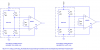
I need to increase the signal output from a loadcell. I would like to use a 10v powersupply used on the loadcell to operate the opamp circuit. I have found some good differential op-amp circuits, but am unsure of what to use for vcc & ground...

Also, what opamp would be good for this application? (10mV full scale need to increase to 5V full scale...)

Thanks for any help you can throw my way!!!!!
 
All the instrumentation op amps are potentially bad for offset because the offset depends a lot on resistor value matching. An actual instrumentation amp chip is much better.

What to use for Vdd and ground?? Whatever voltage the spec sheet says. The spec sheet will also say what acceptable input voltages are in relation to Vdd/gnd.

It is also desirable to simply have a differential ADC going to a microcontroller.
 
What kind of load cell do you have? Can you provide a part number? The IA choice may depend on what you have.
 
Thank you very much, that helps tremendously. To show off my ignorance, however, I have a couple more REALLY dumb questions.

First, what is +/- Rg? Second, would there be any way to tie the output /or input of this device so that I could monitor its accuracy with a pic?

Thank you very much!
 
After I recommended the AD623, I found this calculator.
From the "input resistance" and "output resistance" specs of the load cell, I also calculated what I think the load cell looks like (what a pitiful datasheet). The attached schematic shows two possible orientations for the load cell (note the positions of the resistor values). Either fits the "input resistance" and "output resistance" specs. Hopefully, you have a choice as to which way you orient it. Some of the resistor values will change slightly as the cell is loaded.

I picked this amplifier because it has rail-to-rail output capability, meaning it will go (almost) to zero with no load on the cell, without requiring a negative supply. It is also very inexpensive, and seems to have pretty good specs. You may have to add a post-filter if the output noise is too high.
You can also shift the output "zero" point by connecting the REF input to a reference voltage (don't use a potentiometer unless you buffer it with a voltage follower).
 

Attachments

  • load cell IA.PNG
    load cell IA.PNG
    18.1 KB · Views: 693
heepofajeep said:
Thank you very much, that helps tremendously. To show off my ignorance, however, I have a couple more REALLY dumb questions.

First, what is +/- Rg? Second, would there be any way to tie the output /or input of this device so that I could monitor its accuracy with a pic?

Thank you very much!
What do you mean by "monitor its accuracy with a pic"? You could certainly convert the output to digital with a PIC, and display the results on some sort of display, but you'll need to get help from someone else (Nigel?).
 
Ron H said:
What do you mean by "monitor its accuracy with a pic"? You could certainly convert the output to digital with a PIC, and display the results on some sort of display, but you'll need to get help from someone else (Nigel?).

Easy enough to make a voltmeter with a PIC, and my tutorials show just how to do that - but this is "displaying it's output", not "monitoring it's accuracy".
 
I guess my theory was that the pic could read the power supply voltage being used as the excitation voltage, and then use a simple algorithm to scale the load cell voltage output to the computer as appropriate (if that makes sense). honestly though, this is getting a littel over my head. I know it is possible, and it would be fun to play around with, but just not very feasible for me at the current moment.

What do you guys think the best accuracy achievable with the circuit above would be? I am thinking I will probably just cough up the $300 for a dedicated loadcell amplifier device, but it is always worth exploring all the options :cool:

Thanks again for all your help!
 
can u suggest me any project. m in 6th sem of b.e instrumentation and control and i want to do some project related to it so give me some ideas
 
Status
Not open for further replies.

Latest threads

Back
Top