Continue to Site

Welcome to our site!

Electro Tech is an online community (with over 170,000 members) who enjoy talking about and building electronic circuits, projects and gadgets. To participate you need to register. Registration is free. Click here to register now.

  • Welcome to our site! Electro Tech is an online community (with over 170,000 members) who enjoy talking about and building electronic circuits, projects and gadgets. To participate you need to register. Registration is free. Click here to register now.

Input resistance.

Status
Not open for further replies.
Input resistance is an OK term. It effectively states that it's measured under a DC condition. In generic terms, one can call it input impedance. An scope may have 1 megohm shunted by 20 pf as an input impedance.

An easy experimental way to find it with an amplifier is to put a resistor in series with the input (initially set to zero). Now increase the resistor until the output is 1/2. Take out the resistor and measure. That's the input resistance of the amplifier.

Generally we will know by context.

You can say that my voltmeter has a 10 Megohm input impedance or input Resistance. Older analog meters had an input resistance in units of ohms/volt. Say 50K/volt. So, if you were measuring 2V, your meter would look like a 100 K resistor.

Obviously in the above circuit, you do not know the inductance and capacitance terms, but they should be negligible at the frequency of interest.

Impedance really starts to matter when they are transmission lines. Examples are 50 ohms, 75 ohms, 300 ohms. Cable mismatches in impedance cause reflections in the cable.

I'm not sure I confused you more or not. The important thing is to understand it as the teacher presents it and spit it out that way unless you can prove without a doubt that he is wrong. You tend to learn at the ability that you can comprehend. Later, you may have to totally throw out the concept or you find out the concept only works in that specific case.

e.g. Slope of a line is a special case of slope of a curve.
 
vlad777,

Why isn't this post in one of the technical threads instead of the members lounge?

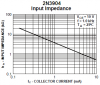
In my school we called input resistance Rpi but I want to ask you
is this widely used, or how should I call it?

No, it is not widely used because its resistance does not follow Ohm's law. The resistance varies all over the map depending on the current used to measure it. Follow what the standard texts call it.

Ratch
 
Why isn't this post in one of the technical threads instead of the members lounge?

Because I thought I was just advertising my site.
I do this when I add something new, and ask you guys if you see a mistake.
(BTW check out the programming demos, I hope someone likes it.)

No, it is not widely used because its resistance does not follow Ohm's law. The resistance varies all over the map depending on the current used to measure it. Follow what the standard texts call it.

I meant, is the symbol Rpi OK?
I found on Wikipedia symbol Z11.

KISS don't get me wrong I went to school years ago.
I know about two kind of slopes of a curve:
instantanious rate of change = slope of a tangent at that point
average rate of change = (y(b)-y(a))/(b-a)
If I am missing something please tell me.

Cheers.
 
Last edited:
I meant, is the symbol Rpi OK?
It's increasingly used to refer to the Raspberry Pi computer :). What does the 'p' stand for in connection with input resistance?
 
Your transistor has negative feedback from the collector to the base of the transistor when there is a source resistance. If the source resistance is very low then there is no negative feedback. The negative feedback reduces the input resistance of the circuit.

Fairchild's datasheet for the 2N3904 transistor has a graph of its input impedance vs its collector current. It is for a "typical" transistor that has "typical" AC current gain.
 

Attachments

  • 2N3904 input impedance.PNG
    2N3904 input impedance.PNG
    15.2 KB · Views: 157
Yes I forgot to put source resistance in the picture.

I looked at Fairchild's datasheet for the 2N3904. It doesn't show how they wired it to get that plot,
but I gather that they just increased base current to get Ic.

And they did it across wide range.
My text talks about small differences in Ib, which makes input resistance almost a constant.
 
The transistor in the input impedance graph is a common emitter type with no emitter resistance. Of course the base current is increased to result in increased collector current.

The current gain amplifies the internal and external emitter resistance of the transistor.

The DC input resistance is hFE x (26/collector current in mA).
The AC input impedance is hfe x (26/collector current in mA).
 
input resistance would be Rin. the example shown above has a capacitor at the input, so Rin would be infinite. input impedance would be Zin, and would be finite, but frequency dependent because of the capacitor and interelectrode and Miller capacitances of the transistor.
 
I have a comment about your alternator page.

Nobody has used a diode trio in an alternator since Motorola first put alternators in cars in about 1960.

In any car built in the last forty or fifty years, the voltage regulator draws the current it uses to excite the alternator field from the battery (switched through the key switch, turned off when key is off, and when the key is in the start position. In the latest cars, the ECU controls the voltage regulator.

Any modern alternator has only six rectifiers, not nine.
 
Status
Not open for further replies.

Latest threads

Back
Top