Electro Tech is an online community (with over 170,000 members) who enjoy talking about and building electronic circuits, projects and gadgets. To participate you need to register. Registration is free. Click here to register now.
Welcome to our site! Electro Tech is an online community (with over 170,000 members) who enjoy talking about and building electronic circuits, projects and gadgets. To participate you need to register. Registration is free. Click here to register now.
I was wondering if anyone of the experts can give me advice on the above.
I need to trigger a counter when a beam of IR light is cut, using a photodiode & phototransistor. The timer circuit is done, I would appreciate any help.
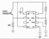
russlk, with the voltage divider like that on pins 6 and 7 isn't that astable mode? wouldn't he want monostable and pin 3 (output) connected to the 7-seg display controller?
No, I did not show the output connection. Astable mode is when pin 2 and 6 are connected. The pulse width is very short when pin6 and 7 are connected, this arrangement widens the pulse width.
Hi everyone,
I have a problem here. I am currently working on a project. It requires me to transmit data from one end to the other using Infra-Red. I've got a 38kHz signal generated using a 555 timer, an IR diode and a receiving module IS1U60. From what i understand, the IS1U60 should allow me to get a High output when theres no signal received and a Low signal where theres a 38kHz waveform. I tried to transmit the 38kHz over to the receiving module but fail to get the desired output as stated. Please help me......its urgent. Thanks
Alvin-Lee: Here is a quote from another website:
Sharp IS1U60 (available at RS, it seems that this IC draws much more current than the others)
Warning: Some users have reported problems with the IS1U60 receiver. It picks up ambient light and is nearly unusable with fluorescent lamps. If ever possible get a different receiver.
I cant get anything transmitted even if I get the emitter to touch the receiver. The circuit is pretty simple. I attach one leg of the Infra-Red to a 38khz signal generated from a 555 timer. On the receiving end, I power up IS1U60 and attach a probe on the output. I get a constant high which means the receiver is not receiving any signal at all.
This site uses cookies to help personalise content, tailor your experience and to keep you logged in if you register.
By continuing to use this site, you are consenting to our use of cookies.