Continue to Site

Welcome to our site!

Electro Tech is an online community (with over 170,000 members) who enjoy talking about and building electronic circuits, projects and gadgets. To participate you need to register. Registration is free. Click here to register now.

  • Welcome to our site! Electro Tech is an online community (with over 170,000 members) who enjoy talking about and building electronic circuits, projects and gadgets. To participate you need to register. Registration is free. Click here to register now.

Infrared detector response time

Status
Not open for further replies.

QuickStrike

New Member
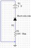
The figure below shows a simple infrared detector circuit.

The response time for a photodiode (T=0.35/2.19RC) is responsible for the fast signal response.

As u can see the formula, if resistance or capacitance or both are made or chosen to be small then the response time will be small (i.e. a fast response time).

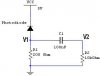
Is there any way to reduce the capacitance of the photodiode besides biasing it (when a voltage is applied to the photodiode, capacitance is reduced). i.e. is there some component that I can connect to the circuit shown below to reduce the capacitance, to acquire a fast response time? Maybe connect a capacitor somewhere!!
 

Attachments

  • image5_105.jpg
    image5_105.jpg
    16.5 KB · Views: 400
I'll take a look at that link, thanks

But problem is that when u reduce the resistance then the voltage across R1 will get small.

1) How much current can a photodiode take?...I couldn't find it in the datasheet

2) At 200 ohm the voltage amplitude is 0.1V, when I increase frequency from 0-2MHz. At 2Mhz the signal begins to have ripples, why?

One more question.

I want to calculate the current passing through the photodiode, how can that current be calculated?.....look at figure below
 

Attachments

  • photodiode1.jpg
    photodiode1.jpg
    7.7 KB · Views: 357
The diode should have a power rating in watts. If it is rated 0.2 watts, then at 5 volts the max DC current is: I = P/E = .2/5 = .04 amps but if the duty cycle is 50%, you could use .08 amps.

Use Ohm's Law to find the current: 0.1 volt across 200 ohms is 500 microamps current. You can get more current by using a stronger light source or more sensitive diode.
 
QuickStrike said:
I want to calculate the current passing through the photodiode, how can that current be calculated?.....look at figure below

I assume you mean the steady-state current; For this, assume C1 is fully charged, hence no current flow through C1/R2. Thus calculate using R1 only; Ignore C1/R2.
 
Status
Not open for further replies.

Latest threads

New Articles From Microcontroller Tips

Back
Top