Electro Tech is an online community (with over 170,000 members) who enjoy talking about and building electronic circuits, projects and gadgets. To participate you need to register. Registration is free. Click here to register now.
Welcome to our site! Electro Tech is an online community (with over 170,000 members) who enjoy talking about and building electronic circuits, projects and gadgets. To participate you need to register. Registration is free. Click here to register now.
Could you please provide me with an article which explains the difference between high side switch and low side switch, regarding the sign of the spikes that are created on the switch when the it switches the coil?
Could you please provide me with an article which explains the difference between high side switch and low side switch, regarding the sign of the spikes that are created on the switch when the it switches the coil?
Relative to the steady-state voltage when the switch is on, when the switch goes off, the spike will go positive for low side switches and negative for high side switches. This is why you generally see a reverse-biased diode across the inductor. The diode will be briefly forward-biased when the switch goes off, conducting the current that continues to flow in the inductor until the magnetic field has collapsed. This clamps the voltage across the inductor, protecting the switch from overvoltage.
A properly chosen shunt capacitor can also help smooth things out, the cap will look like a dead short to the peak pulses, and can also serve to buffer a PWM pulses from a driving circuit. I've seen ceramics used on both motors and relays just as a 'might as well' sort of precaution, even with diodes, the capacitor will start conducting the sharpest front of a spike even before the diode reaches conductance. It's best simulated or tested from your real world circuit. Snubber circuits can be quiet advanced. Or as simple as the reverse biased diode, or ceramic bypass cap.
I have seen series RC snubbers, but a capacitor will resonate with the relay coil's inductance. Unless the Q of the coil at the resonant frequency is low, the voltage across the coil will ring, and could still break down the transistor.
Thanks,
When you speak about resonance, what is the frequency that you consider?
I mean we're talking about a DC circuit, execpt for the switching part, so what is the frequency you're talking about?
Thanks,
When you speak about resonance, what is the frequency that you consider?
I mean we're talking about a DC circuit, execpt for the switching part, so what is the frequency you're talking about?
Relay coils have significant inductance, but I have never seen it specified in a datasheet.
When the relay is de-energized, the coil current cannot change instantaneously. If there is no place for the decaying current to flow, a large voltage spike will be created. If there is an alternate path (diode, capacitor), the current will take that path. If the alternate path is a capacitor, the current will "slosh" back and forth between the coil and the cap, creating a damped sine wave. The frequency if that sine wave will be F=1/(2Π√LC), where L is the inductance of the coil and C is the parallel combination of the external cap and the stray capacitance of the coil.
BTW, the stray capacitance of the coil will almost certainly be sufficient to absorb the current until the "diode reaches conductance".
What will cause the current to become a sine wave?
I mean if you will solve a differential equation of a series RLC circuit, with initial conditions :
I_L(t=0) = Relay's_current
V_C(t=0) = 0V (if the switch is low side) or Relay's_voltage (if switch is high side)
Then you'll get a sine wave that its frequency is what you said?
If it does, whats the problem with that, as long as the sine wave is dying out?
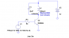
Here is a simulation. You will get different results, depending on the inductance and resistance of the coil, and the shunt capacitance.
In this example, the positive peak will break down the collector-base junction, and the negative pulse will break down the base-emitter junction.
I'm not saying the right combinations of parts won't work, just that you have to be aware of the dangers.
Anticipating a question: You will get the same results if the cap is tied to ground instead of Vcc.
I can't imagine why anyone would use a capacitor, when a diode is a much better solution.
A case against a straight diode is slower relay dropout time in situations where that matters, and high peak surge current through the diode which can be an EMI issue in some sensitive cases, particularly if the diode must be placed across the switch, further away from the relay coil. If the polarity of the coil is switched, such as in some latching relays, the diodes must be placed across the switching device(s). In such cases back-to-back zener diodes may be the better choice. As mentioned, the RC snubber is another.
For the low side switch:
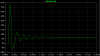
When the circuit "rings" (goes into damped oscillation), the voltage first goes positive, due to the fact that the current which was flowing in the inductor continues to flow - into the capacitor. The L and C (this is called a tank circuit) resonate, so the voltage waveform becomes a damped sinusoid, and thus eventually goes negative. When it reaches ≈-0.7V, the collector-base junction becomes forward biased, and the base resistor absorbs much of the energy that is circulating in the tank, distorting the waveform. Succeeding cycles of the waveform do not swing low enough to forward bias the C-B junction, so the decay in the sine wave amplitude is determined by L, C, and the resistance of the coil (500 ohms in this case).
Note that most Spice transistor models do not model breakdown phenomena. If they did, this waveform would look considerably different.
This site uses cookies to help personalise content, tailor your experience and to keep you logged in if you register.
By continuing to use this site, you are consenting to our use of cookies.