Continue to Site

Welcome to our site!

Electro Tech is an online community (with over 170,000 members) who enjoy talking about and building electronic circuits, projects and gadgets. To participate you need to register. Registration is free. Click here to register now.

  • Welcome to our site! Electro Tech is an online community (with over 170,000 members) who enjoy talking about and building electronic circuits, projects and gadgets. To participate you need to register. Registration is free. Click here to register now.

Infocus projector no power

Status
Not open for further replies.

1-3-2-4

Member
It's the IN116 model

I have the power supply out right now and with a power cable plugged in I see no voltage over the main fuse.


Where should I check first?

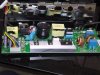
the stuff on the heatsink

k20a60u & fsu10a60 and the bridge rectifier D10XB60b

+ to - on the bridge rectifier I'm getting 164 V
 

Attachments

  • DSC00648.JPG
    DSC00648.JPG
    1.1 MB · Views: 980
Last edited:
Looks like a typical standard switching power supply. Have a look at this pdf. My bet is a cap with a high ESR
 

Attachments

  • slva085.pdf
    71.2 KB · Views: 481
I ordered all new Panasonic caps to replace the Elite branded.

CAP ALUM 47UF 25V 20% RADIAL
CAP ALUM 10UF 50V 20% RADIAL
CAP ALUM 47UF 35V 20% RADIAL
CAP ALUM 22UF 50V 20% RADIAL
CAP ALUM 1000UF 25V 20% RADIAL (2)
CAP ALUM 150UF 450V 20% SNAP

MR4010 IC seems like the gate is stuck on and conducting which would account for it going to 60 C in less then 3 minutes with no load.

I will have to get a replacement and check.
 

Attachments

  • MR4010.jpg
    MR4010.jpg
    211.1 KB · Views: 867
Last edited:
So I replaced the caps and replaced the IC thats MR201 and still no dice, it heats up to 65C soon after it plugged in.. It's so simple but so hard, I've been thinking here for a few what would prevent or keep me from getting a stand by voltage from a SMPS it should be giving me from what it seems 5V and 12V.

Also what kind of transformer is this?? I've never seen one with 4 legs on one side and 6 on the other..

And I assume since IC201 is getting hot so quick something must be shorted?
 
Wonder if it's just cheaper to buy a new power supply. Could be anything wrong with it etc. But sounds like you are driven to fix the thing:). Did you have a look at the pdf I uploaded, might be of assistance.
 
haha the cost of a new power supply is pretty much the cost of a new projector as, no projectors for parts of my model exist and the power supply is not sold alone.

And this board is only but so big.. I will say however this makes me hate on switch mode power supplies..

I have looked at the pdf you uploaded, I'm not sure if hooking my scope up is going to tell me much and I'm a little worried about taking the scope on something that's at 160VDC.

You know I was thinking something.. I assume since I see 164VDC on the primary side I can safety say those filter caps are fine? re-reading that pdf again the two blue caps near the High-voltage symbol.. is it possible for film caps to short? How would they read on a meter?
 
Last edited:
Well looking at the schematic there is not alot of components,so may be worth replacing the diodes and semi';s. There could also be a shorted or open resistor. for I think it would be quite rare if one of the transformers or inductors were faulty. Don't be snooping around with a scope unless you isolate the power supply, could damage your scope.

https://youtu.be/xaELqAo4kkQ

Yeah I did not isolate it and I ended up blowing the fuse on the board I'm trying to fix I just took out the Schottky barrier diode and tested it and it checks out fine, looks like I will be buying a SMD hot air station.

I tested that 3W 0.36 Ohm resistor and it checks out fine as well.
 
Here is a tip on testing in-circuit with resistors.

https://www.antiqueradios.com/forums/viewtopic.php?f=6&t=181178

p.s don't need a hot air machine, a pair of tweezers and a fine tip iron will work fine.

Here is one confusing me.. I have a SMD calculator on my phone but it says "E095" so should that be 55 Ohm?

*EDIT

Hmm.. I'm looking at a FET here.. it's part number K20A60U Can anyone confirm that's a Toshiba FET?

I took it out of circuit and I can't get the gate to open, my meter puts out 1.5V in diode test

I followed this which I used in the past to find two Mosfets that were shorted.

https://www.4qdtec.com/mostest.html
 
Last edited:
Status
Not open for further replies.

Latest threads

Back
Top