Hi..
i've got a ciggeratte lighter powered 5v switching regulator (to emulate the charging facility of a USB port in the car) and I wanted to make a duplicate of it.
Having figured out the heart was a switching reg MC34063, I soon discovered that it was a generic reference design the manufacturer had used.
It takes in about 12v - 14.4v (theoretically) and puts out 5v, 850mA (says on the label).
Now, i've gotten all the values of the parts save one - the inductor.
I know there's a method of calculating the inductance value but the problem is I can't actually figure out how.. the datasheet askes for Vsat (voltage saturation?) and it's not something i've done before, so I'm rather clueless.
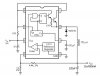
Can someone recommend a method/solution/value for this? The enclosed circut is how everything is pretty much set up, under the "medium power" design in the PDF.
https://www.electro-tech-online.com/custompdfs/2005/04/AN920-DPDF.pdf
Also, it would be nice to explain the particular significance of the inductor in this circut (being in Malaysia, you either have to buy 10 pieces at an extremely inflated price off RS, or.. scrounge around miserably in the dotting electronic shops around) as per reason it would be very pleasant to scrap it.
Lastly, there was something unusual - the manufacturer had put a bit of heatshrink around one of the capacitors - the 47uF one going from +ve to ground. There are no moving parts/naked wires, any idea of its purpose?
Thanks!")
i've got a ciggeratte lighter powered 5v switching regulator (to emulate the charging facility of a USB port in the car) and I wanted to make a duplicate of it.
Having figured out the heart was a switching reg MC34063, I soon discovered that it was a generic reference design the manufacturer had used.
It takes in about 12v - 14.4v (theoretically) and puts out 5v, 850mA (says on the label).
Now, i've gotten all the values of the parts save one - the inductor.
I know there's a method of calculating the inductance value but the problem is I can't actually figure out how.. the datasheet askes for Vsat (voltage saturation?) and it's not something i've done before, so I'm rather clueless.
Can someone recommend a method/solution/value for this? The enclosed circut is how everything is pretty much set up, under the "medium power" design in the PDF.
https://www.electro-tech-online.com/custompdfs/2005/04/AN920-DPDF.pdf
Also, it would be nice to explain the particular significance of the inductor in this circut (being in Malaysia, you either have to buy 10 pieces at an extremely inflated price off RS, or.. scrounge around miserably in the dotting electronic shops around) as per reason it would be very pleasant to scrap it.
Lastly, there was something unusual - the manufacturer had put a bit of heatshrink around one of the capacitors - the 47uF one going from +ve to ground. There are no moving parts/naked wires, any idea of its purpose?
Thanks!