kinarfi
Well-Known Member
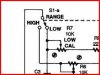
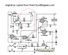
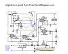
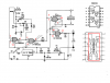
Has anyone built on of these? I tried building a Simulation and it didn't work. It calls for a 74HC132, I plan to use a CD4093BCN which has a different pin configuration because I have it. Does any one have an understanding of how it works?
Thanks,
Kinarfi
Where I got the design, https://freecircuitdiagram.com/2009/05/12/inductance-meter-circuit/
Thanks,
Kinarfi
Where I got the design, https://freecircuitdiagram.com/2009/05/12/inductance-meter-circuit/
Attachments
Last edited: