Hi all,
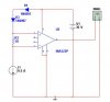
I want to use the INA122 as a current shunt amplifier. I have attached the schematic here. I want to know before I connect this to power whether it is correct or not. The two diodes are to drop the voltage to the + and - pins by about 1.2V
BTW when I simulate the circuit it does not work !!!!!!!!!!!!!!!!

 !!!!!!!!!!!!!!