Continue to Site

Welcome to our site!

Electro Tech is an online community (with over 170,000 members) who enjoy talking about and building electronic circuits, projects and gadgets. To participate you need to register. Registration is free. Click here to register now.

  • Welcome to our site! Electro Tech is an online community (with over 170,000 members) who enjoy talking about and building electronic circuits, projects and gadgets. To participate you need to register. Registration is free. Click here to register now.

in trouble with LCD (JHD162A)

Status
Not open for further replies.

smileguitar

New Member
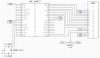
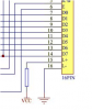
Hello, recently doing a project using LCD-JHD162A with PIC 16F877. Everything was done, but the LCD cannot display any character. It really frustrated. Hopefully, somebody can kindly give some comment. The coding is shown as below: (SCHEMATIC DIAGRAM AT http://www.cytron.com.my/Images/project/schematicPR3.gif)

LIST P=16F877

#INCLUDE <P16F877.INC>

__CONFIG 0X3F32

;========================MACRO ===========================

BANK0 MACRO
BCF STATUS,RP0
BCF
ENDM

BANK1 MACRO
BSF STATUS,RP0
BCF STATUS,RP1
ENDM


CLOCK_E MACRO
BSF PORTD,3
CALL DELAY2
BCF PORTD,3
ENDM

;========== VARIABLE ======================================

D1 EQU 0X20
D2 EQU 0X21
D3 EQU 0X22
D4 EQU 0X23
D5 EQU 0X24
D6 EQU 0X25

;=========================================================
;========== MAIN PROGRAMME ===============================
;=========================================================

ORG 0X000
GOTO START

STOP ORG 0X004
GOTO STOP

START BANK0
CLRF PORTA
CLRF PORTB
CLRF PORTC
CLRF PORTD
CLRF PORTE

BANK1
MOVLW 0x06
MOVWF ADCON1
CLRF TRISA
CLRF TRISB
CLRF TRISC
CLRF TRISD
CLRF TRISE

BANK0
CLRF PORTB

;*****************LCD INITIALIZED****************************

CALL DELAY1
BCF PORTD,2
MOVLW B'00110000'
MOVWF PORTB
CLOCK_E

CALL DELAY2
MOVLW B'00001101'
MOVWF PORTB
CLOCK_E

CALL DELAY3
MOVLW B'00111000'
MOVWF PORTB
CLOCK_E
MOVLW B'00000001'
MOVWF PORTB
CLOCK_E
MOVLW B'00000110'
MOVWF PORTB
CLOCK_E

;****************MESSAGES DISPLAY IN LINE 1 ******************

BSF PORTD,2
MOVLW H'59'
MOVWF PORTB ;DISPLAY "YES"
CLOCK_E
MOVLW H'45'
MOVWF PORTB
CLOCK_E
MOVLW H'53'
MOVWF PORTB
CLOCK_E

;****************SET LCD TO SECOND LINE**********************

BCF PORTD,2
MOVLW B'11000000'
MOVWF PORTB
CLOCK_E

;****************MESSAGES DISPLAY IN LINE 2******************

BSF PORTD,2
MOVLW H'31'
MOVWF PORTB ;DISPLAY123
CLOCK_E
MOVLW H'32'
MOVWF PORTB
CLOCK_E
MOVLW H'33'
MOVWF PORTB
CLOCK_E

GOTO $-1

;=========================================================
;========== SUBROUTINE FOR DELAY ===========================
;=========================================================

DELAY1 MOVLW D'65' ;DELAY 50ms
MOVWF D2
MOVLW D'238'
MOVWF D1
LOOP1 DECFSZ D1,1
GOTO LOOP1
DECFSZ D2,1
GOTO LOOP1
RETURN

DELAY2 MOVLW D'13' ;DELAY 10ms
MOVWF D4
MOVLW D'251'
MOVWF D3
LOOP2 DECFSZ D3,1
GOTO LOOP2
DECFSZ D4,1
GOTO LOOP2
RETURN

DELAY3 MOVLW D'1' ;DELAY 100us
MOVWF D6
MOVLW D'31'
MOVWF D5
LOOP3 DECFSZ D5,1
GOTO LOOP3
DECFSZ D6,1
GOTO LOOP3
RETURN

END


seems the coding I typed in is hard to see, I've been attached.
 

Attachments

  • LCD.asm
    2.9 KB · Views: 350
Last edited:
I've simulated the LCD coding by simulation software, but it cannot apply to my LCD circuit. I've check my connection, there is no problem as well. Also, I tried with the LED blinking, it can work, just cannot display on the LCD. I've totally lost......:(
 
hi,
Tried running your code on my simulator, it looks as though the LCD controller is the Hitachi HD44780.
All I get on the LCD is '23' on the second line.
Where are the RS and R/W lines connected?

I dont see any reference to these control lines in your program.

Also you have enclosed your web link in 'brackets' I cannot call it!.
EDIT:
Managed to get the gif, see that RS is on RD2 and R/W is low.
 
Last edited:
hi,
Your program output on the simulator.

Do you have square pixel blocks on the LCD when you adjust the Contrast pot?
 
Last edited:
First, I feel very grateful about ur help.... THANKS :)

Yes, I set the RS line on RD2 and I connect the R/W to ground.

erm....what do you mean by square pixel blocks?
 
smileguitar said:
First, I feel very grateful about ur help.... THANKS :)

Yes, I set the RS line on RD2 and I connect the R/W to ground.

erm....what do you mean by square pixel blocks?

hi,
The contrast pot to VEE, when adjusted to a given value should cause the LCD to display black squares at the positions where the characters should normally appear.
If you cannot adjust the contrast pot to show these blocks, then check the wiring to the LCD [ the power +5V and 0V and the VEE contrast, also check the voltages on these pins]
 
Yes, I've double check each connection pin of LCD, and the contrast pot. I'm using 4.7kohm variable resister. But I've no idea why the LCD still cannot display any character even a cursor. At first, I set the variable resister around 4.2kohm, so I think it was high ohm to cause the problem. I reseted it lower, LCD still doesn't work as what have been expected.
 
smileguitar said:
Yes, I've double check each connection pin of LCD, and the contrast pot. I'm using 4.7kohm variable resister. But I've no idea why the LCD still cannot display any character even a cursor. At first, I set the variable resister around 4.2kohm, so I think it was high ohm to cause the problem. I reseted it lower, LCD still doesn't work as what have been expected.

Hi,
Try the attached modified program, the changes are marked with '++++'
 
Last edited:
ericgibbs said:
Hi,
Try the attached modified program, the changes are marked with '++++'


Hi, I have simulated the modified program, there is error occurred on my simulator software. Is there ok if I test it in LCD circuit directly?

Actually I'm wondering why my program cannot apply to the LCD, while it is correct. The connection pins also connect to proper way. Is that my program doesn't suit to the circuit?

The LCD schematic diagram is attached:
 

Attachments

  • LCD schematic diagram.JPG
    LCD schematic diagram.JPG
    120.5 KB · Views: 1,601
Last edited:
smileguitar said:
Hi, I have simulated the modified program, there is error occurred on my simulator software. Is there ok if I test it in LCD circuit directly?

Actually I'm wondering why my program cannot apply to the LCD, while it is correct. The connection pins also connect to proper way. Is that my program doesn't suit to the circuit?

The LCD schematic diagram is attached:

Hi,
I will rewire my test board to suit your PIC pinouts to the LCD, then load your program into a 16F877 and give it a run.

Do you have a datasheet for the LCD module, just in case there are any differences between the Hitachi and your LCD controller.?

To be sure your PIC setup is OK, write a simple LED ON/OFF program, this will check that your PIC16F877 is actually working.:rolleyes:
 
hi,
Downloaded the datasheet, they are the same.

Modified my project board to suit your wiring.
Programmed a PIC 16F877 with your program.
The Delays are too short, as you are not testing Dbit7 for BUSY, the LCD controller is not initialising correctly.
As a quick check increased your program delays by a factor of 3 [ called the delays 3 times each].
The LCD works OK.
Displays my test data:
Yes
Hello

With no problems.:)
Did you manage to see any pixel blocks while adjusting the contrast pot, its MOST important that the blocks can be made visible!!

EDITED: added a simple LCD asm program, it should display on LCD line no1:
"Line1"
Its the compiled output asm from the Oshonsoft Basic compiler.
Its been loaded into a PIC16F877 and it works, so if you cannot get a display, the problem is most likely your hardware.
 
Last edited:
ericgibbs said:
hi,
Downloaded the datasheet, they are the same.

Modified my project board to suit your wiring.
Programmed a PIC 16F877 with your program.
The Delays are too short, as you are not testing Dbit7 for BUSY, the LCD controller is not initialising correctly.
As a quick check increased your program delays by a factor of 3 [ called the delays 3 times each].
The LCD works OK.
Displays my test data:
Yes
Hello

With no problems.:)
Did you manage to see any pixel blocks while adjusting the contrast pot, its MOST important that the blocks can be made visible!!

EDITED: added a simple LCD asm program, it should display on LCD line no1:
"Line1"
Its the compiled output asm from the Oshonsoft Basic compiler.
Its been loaded into a PIC16F877 and it works, so if you cannot get a display, the problem is most likely your hardware.

Hi, sorry for late reply.

what do you mean by Dbit7 for busy?

I was using 4.7kohm variable resister to adjust the contrast pot. when I was adjusting, there is nothing come out from LCD. The LCD only on the light.

Today, I tested the LCD hardware with your edidted program. But failed. At first, some pixel blocks came out, but gone after few minutes, LCD light still on....Is that my LCD or connection problem?I was connect the Vee to ground, could I connect by this way? Is it correct?

I'll attach the LCD datasheet that I'm using, and could you explain why my delay time and initialising of LCD is not correct since I follow the datasheet. I'm sorry, my knowledge about PIC microcontroller is limited. Hopefully I can gain some knowledge from you. Thanks!
 

Attachments

  • hd44780u.pdf
    278.2 KB · Views: 360
Last edited:
You don't need the PIC to test if your LCD module is ok.
After removing the PIC from its socket and giving power to the LCD, you should see a row of black rectangular boxes, as already pointed out. If the LCD passes this test, you can use it in your circuit and write the firmware.

Perhaps the backlight is causing troubles? In the schematic you posted I don't see a current limiting resistor between pin 15 and Vdd of the LCD module and it might be drawing too much current and behaving unpredictably? Just an idea though... since you say that you've double-checked the wiring and I trust Eric as far as the program is concernerd :)


Happy Holidays
 
eng1 said:
You don't need the PIC to test if your LCD module is ok.
After removing the PIC from its socket and giving power to the LCD, you should see a row of black rectangular boxes, as already pointed out. If the LCD passes this test, you can use it in your circuit and write the firmware.

Perhaps the backlight is causing troubles? In the schematic you posted I don't see a current limiting resistor between pin 15 and Vdd of the LCD module and it might be drawing too much current and behaving unpredictably? Just an idea though... since you say that you've double-checked the wiring and I trust Eric as far as the program is concernerd :)


Happy Holidays

erm.... What do you mean by the backlight is causing troubles?

So, I've to connect a resister between pin 15? What about the value of resister? Is between 1kohm to 10kohm?

Thanks for your suggestion!
 
The value depends on the LEDs' current, that is usually specified in the datasheet of the LCD module. If you're assembling this circuit on a breadboard, just leave pins 15 and 16 of the LCD floating (no backlight) and see what happens.
 

Attachments

  • resistor.png
    resistor.png
    42.8 KB · Views: 1,273
Last edited:
eng1 said:
The value depends on the LEDs' current, that is usually specified in the datasheet of the LCD module. If you're assembling this circuit on a breadboard, just leave pins 15 and 16 of the LCD floating (no backlight) and see what happens.

Ok, I'll try it.
Thanks!
 
smileguitar said:
Ok, I'll try it.
Thanks!
hi,
eng1 and I, consider the possibilty that without the backlight LED current limiting resistor, the +5V supply line could be getting pulled down, if held down long enough the +5V regulator could be going into thermal shutdown.

You said that you had the pixel blocks for a while then they faded away, this again suggests a possible power supply problem.

Do as eng1 suggests, disconnect the LCD backlight..:)
 
ericgibbs said:
hi,
eng1 and I, consider the possibilty that without the backlight LED current limiting resistor, the +5V supply line could be getting pulled down, if held down long enough the +5V regulator could be going into thermal shutdown.

You said that you had the pixel blocks for a while then they faded away, this again suggests a possible power supply problem.

Do as eng1 suggests, disconnect the LCD backlight..:)

I got it, thanks! :)
 
ericgibbs said:
hi,
eng1 and I, consider the possibilty that without the backlight LED current limiting resistor, the +5V supply line could be getting pulled down, if held down long enough the +5V regulator could be going into thermal shutdown.

You said that you had the pixel blocks for a while then they faded away, this again suggests a possible power supply problem.

Do as eng1 suggests, disconnect the LCD backlight..:)

why not power the back-lit from unregulated voltage and change the current limit resistor to a suitable value?
 
mvs sarma said:
why not power the back-lit from unregulated voltage and change the current limit resistor to a suitable value?

hi Sarma,
We are trying to debug his project, the problem is that we are not sure if the LCD is faulty, the wiring wrong or the power supply/backlight is at fault.
The programs have been run OK in PIC's on my system OK.

We are suggesting removing the backlight as a possible cause of his problem, its not needed at this stage.
When the LCD works then he can put the backlight on...:)
 
Status
Not open for further replies.

Latest threads

Back
Top