rosscopico0
New Member
Hi all,
I am working on a project to fit a rtd pt1000 into the grouphead of an espresso machine and measure with high accuracy (0.1C-0.5C) the water just before it reaches the coffee.
Im planning to use a 4 wire rtd, to minimize switching noise (is this correct?)
I know I require a constant current source for excitation. From what I have read, I require 1mA or less, to prevent self heating errors, I was thinking around 250uA-500uA.
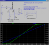
My range of interest is 85C to 95C which corresponds to 1328Ω to 1366Ω, so with such a small difference in resistance, the accuracy of the current source and signal conditioning is quite important.
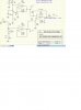
Using 5Spice, Ive developed a circuit that I think could work, I have attached it below for critique.
The output of the interface cct will go to an Arduino analog 10 bit input.
Just need to figure out the constant current part.....help!!
I am working on a project to fit a rtd pt1000 into the grouphead of an espresso machine and measure with high accuracy (0.1C-0.5C) the water just before it reaches the coffee.
Im planning to use a 4 wire rtd, to minimize switching noise (is this correct?)
I know I require a constant current source for excitation. From what I have read, I require 1mA or less, to prevent self heating errors, I was thinking around 250uA-500uA.
My range of interest is 85C to 95C which corresponds to 1328Ω to 1366Ω, so with such a small difference in resistance, the accuracy of the current source and signal conditioning is quite important.
Using 5Spice, Ive developed a circuit that I think could work, I have attached it below for critique.
The output of the interface cct will go to an Arduino analog 10 bit input.
Just need to figure out the constant current part.....help!!