Continue to Site

Welcome to our site!

Electro Tech is an online community (with over 170,000 members) who enjoy talking about and building electronic circuits, projects and gadgets. To participate you need to register. Registration is free. Click here to register now.

  • Welcome to our site! Electro Tech is an online community (with over 170,000 members) who enjoy talking about and building electronic circuits, projects and gadgets. To participate you need to register. Registration is free. Click here to register now.

IMPORTANT >> Make square wave lag by 90 degrees?

Status
Not open for further replies.

Roff

Well-Known Member
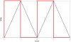
Why is this thread locked? As I said, there is an easy way to do this. No one seemed to recognize that the output waveform (see below) is the derivative of the input. A differentiator is very simple. I have posted one below, followed by a logic level translator (the transistor). The value of the capacitor is selected depending on the slew rate of the input.

C1=200nF/Vpp, where Vpp is the peak to peak amplitude of the triangle wave. This will yield +/-2V at the output of the op amp, which is used to switch the transistor.
 

Attachments

  • differentiator.gif
    differentiator.gif
    5.9 KB · Views: 742
  • waveforms_188.jpg
    waveforms_188.jpg
    28.8 KB · Views: 1,795
differentiator

I noticed, but the thread was locked (why??). A differentiator followed by an inverter gives the correct phase, as Ron pointed out.

http://www.ecircuitcenter.com/Circuits/opdfr/opdfr.htm

My thought was to use a dual, single supply op-amp like the LM358 for this, it's hard to get much simpler than Ron's circuit. The trouble with using a comparator like the LM339 is that the signal phasing comes out wrong (the comparator switches at mid-point of the triangle wave).
 
Status
Not open for further replies.

New Articles From Microcontroller Tips

Back
Top