Electro Tech is an online community (with over 170,000 members) who enjoy talking about and building electronic circuits, projects and gadgets. To participate you need to register. Registration is free. Click here to register now.
Welcome to our site! Electro Tech is an online community (with over 170,000 members) who enjoy talking about and building electronic circuits, projects and gadgets. To participate you need to register. Registration is free. Click here to register now.
Please tell us what you are trying to do, and why?. It's pointless offering suggestions when we don't know what it's supposed to be doing, a generic question can have too many answers - many of which may be totally irrelevent to your question.
Particularly as you've jumped from doubling the frequency to phase lag, for (presumably) the same problem!.
Please tell us what you are trying to do, and why?. It's pointless offering suggestions when we don't know what it's supposed to be doing, a generic question can have too many answers - many of which may be totally irrelevent to your question.
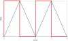
See attachment, i have blue waveform i need to convert it into red waveform. The phase alignments between the two waveforms must be same as shown in the image. This is why i cant just use a 555 timer.
EDIT: I was thinking along the lines of a zero-crossing detector that triggers a 1 second pulse from a 555 monostable, but dont know to do that.
If you want the square waveform lag the triangle waveform the easiest way is to pass the teh squarewave through a lowpass RC filter (best bet is to use a veriable resistor for this bit then fix the value later)
Then this new "curvy" waveform pass through one gate from a 74HC14 HEX Schmitt trigger inverter (and then another one of the inverters otherwise you have an extra 180deg shift to deal with).
The 74HC14 schmitt trigger action will regenerate a square wave from teh curvy one, but due to the (internal) hysteresis it will be delayed. How much it is delayed depends on the time constant of the RC
I us this cct all the time to make intelocks between PWM for quick motor-drives
It was based on this statement that I suggested using the RC - logic Schmitt trigger to delay the square wave.
If you want to make the squarewave use a comparator with +ve feedback to make a shmitt-trigger that way you can have wide hysteresis to generate teh squarewave
I'd still like to know what it's for, and why it needs the accurate phase relationship - or even to confirm that it does!.
But for a single chip, cheap solution, you could use a PIC12F675, 8 pin PIC with 10 bit A2D.
Sample the triangle wave coming in, if it's below a certain (low) value set the output high, if it's above a certain (high) value set the ouput low. This will give the correct phase relationship - and with the slow frequency of the triangle wave will be much more than accurate enough.
Perhaps a bit of overkill, but it only requires one cheap 8 pin PIC, and no other components (assuming you already have a 5V supply - but any solution will require a supply).
Nigel has the easiest option, but I have to argue that the switching point should be decided by a change of direction of the a/d reading rather than a fixed point. The accuracy will be a bit better than half a degree and the settling time will be within half a cycle. An alternative using a phase locked loop can be more accurate, but will take a long time to settle(minutes) after any disturbance or small change of frequency.
Nigel has the easiest option, but I have to argue that the switching point should be decided by a change of direction of the a/d reading rather than a fixed point. The accuracy will be a bit better than half a degree and the settling time will be within half a cycle. An alternative using a phase locked loop can be more accurate, but will take a long time to settle(minutes) after any disturbance or small change of frequency.
I fail to see how the PIC solution is the best/easiest?.
We don't even know if he has the means to program the PIC. If he doesn't then it is alot more fuss.
What is more simple than an LM139, abt 3resistors and depending on the amplitude of the tiangle wave w.r.t. the amplitude of the squarewave possible use of +/-15V supply and a zener diode.
That is soo much more simpler than any code out there but I suppose it is what you are more comfortable with. I personally would not go anywhere near any software unless I really cannot avoid it for a project. When you see a 50kW drive blow up due to a softy forgetting to put upper/lower limits into a software inteface for a ballscrew limit and see him accedently enter in a demand that is equal to 3miles and the ballscrew is only 1meter long and see my drive try to accel off to 3miles and break through the steel endstops of the ballscrew as it tries to accel off to 3miles and then blow up you dont trust software for anything
Is your square wave output a logic signal, like maybe zero to 5 volts? The solution, I believe, can much simpler than those posted thus far. What is the peak-to-peak amplitude of your triangle wave?
This site uses cookies to help personalise content, tailor your experience and to keep you logged in if you register.
By continuing to use this site, you are consenting to our use of cookies.