Electro Tech is an online community (with over 170,000 members) who enjoy talking about and building electronic circuits, projects and gadgets. To participate you need to register. Registration is free. Click here to register now.
Welcome to our site! Electro Tech is an online community (with over 170,000 members) who enjoy talking about and building electronic circuits, projects and gadgets. To participate you need to register. Registration is free. Click here to register now.
Hi all, I am currently building a small-scale solar charger and I am getting confused about the impedance matching between the solar panel and battery.
How can I measure the impedances of solar panel and battery and match them in order to get the maximum power ? many thx
Thanks for ur all replies. I`d like to know how to measure the impedances of my source(solar panel) and load(battery). Should I use Smith chart or something else ? Is there any easiest way to do the job ? many thxxxxx
Thanks for ur all replies. I`d like to know how to measure the impedances of my source(solar panel) and load(battery). Should I use Smith chart or something else ? Is there any easiest way to do the job ? many thxxxxx
If you are hell bent on measuring the "impedance", just use a variable load resistance and measure the voltage and current as the load resistance varies.
Draw a graph of volts/current, the slope of the graph will give you the "impedance" (resistance actually as this is just a DC situation).
The reality is that you dont match impedances in power transmission. While a matched impedance will give maximum power transfer, it is also only 50% efficient - do the maths on a few examples and you will see.
For best EFFICIENCY, the source impedance should be low compared with the load impedance.
Again, do some maths and you will see that for a matched load and source, for every watt supplied to the load, there is one watt dissipated in the source.
Rio FUN, I will give you a job any day, as my entertainments manager!
Thanks for the laugh, it made a good day even better!
All joking aside, a Smith Chart is used for RF, not DC.
Unless your solar cells and batteries work at RF and are connected by a nice long transmission line, the Smith chart wont do much for you.
For best EFFICIENCY, the source impedance should be low compared with the load impedance.
Again, do some maths and you will see that for a matched load and source, for every watt supplied to the load, there is one watt dissipated in the source.
Except you're not wanting maximum efficiency, you're wanting maximum power transfer, which as you quite rightly say wastes (at least) 50% in the source. However, it's the most efficient as well, all other methods will provide LESS power to the load.
Not quite sure how this would work out with a solar cell, I guess it all depends on the ratings of the solar cell.
However, if you tried to put a "matched load" onto something like a car battery I think there would be a lot of sparks, a big bang and a shower of boiling sulphuric acid , as several kilowatts are dissipated in the battery.
But, as noted, you can't directly match the solar cell impedance to the battery impedance. You need some type of electronic power circuit in between. That circuit provides a matched load to the solar panel and converts the power to the correct level to charge the battery.
Charging from solar panels is complicated: # panels in series = battery voltage +10->25%. Overvolt margin is based on average expected light intensity & battery type.
What we found to be the tough call was panel area for average current vs average demand on a cyclic basis. Latitude & climate also play in.
We developed a product that worked ok in northern US mid-summer & year-round down south. It's an warm weather object, so northern winter isn't an issue. It still took us a While to hit this balance. It's too easy to underestimate storage capacity & (especially) recharging requirements vs average load. Good Hunting... <<<)))
But, as noted, you can't directly match the solar cell impedance to the battery impedance. You need some type of electronic power circuit in between. That circuit provides a matched load to the solar panel and converts the power to the correct level to charge the battery.
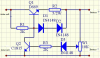
Hi all, I did some calculations and from the graph of volts/current obtained, it gave me the Maximum Power when 2.5V@10K ohms. I built a charge regulator which provide stable 1.44V charging voltage between solar panel and battery. Any suggestions on improving the efficiency?
Hi all, I did some calculations and from the graph of volts/current obtained, it gave me the Maximum Power when 2.5V@10K ohms. I built a charge regulator which provide stable 1.44V charging voltage between solar panel and battery. Any suggestions on improving the efficiency?
Here is the circuit diagram. The solar panel is 6V@200mA and the data was measured when the solar panel was in the inside room instead of in full sunlight.
A silicon solar cell is an illumination based current source, clamped by its inherent diode. There is some series resistance, and depending on the quality of cell, some shunt resistance. For good quality cell the shunt resistance is relatively minor. **broken link removed**
With no load, all the illumination generated current is shunted down the inherent diode giving it an open circuit voltage of about 0.65 vdc. As with a silicon diode, the inherent diode has a negative temp coefficient of -2 mV per deg C.
For a given illumination level the current will remain relatively constant (depending on shunt resistance of cell) from point where inherent diode starts conduction down to zero volts across cell. Maximum power point is where the inherent diode barely conducts. This is about 0.52 vdc at 25 deg C.
As a current source, cell 'impedance' is very high, until inherent diode starts to conduct.
This site uses cookies to help personalise content, tailor your experience and to keep you logged in if you register.
By continuing to use this site, you are consenting to our use of cookies.