Continue to Site

Welcome to our site!

Electro Tech is an online community (with over 170,000 members) who enjoy talking about and building electronic circuits, projects and gadgets. To participate you need to register. Registration is free. Click here to register now.

  • Welcome to our site! Electro Tech is an online community (with over 170,000 members) who enjoy talking about and building electronic circuits, projects and gadgets. To participate you need to register. Registration is free. Click here to register now.

Impedance Matching Problem

Status
Not open for further replies.

PGrogan

New Member
Hi,

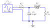
I'm trying to make an impedence matching circuit. My input resistance is 1,5K and my output load is 330 (see schematic below). To be sure that my circuit works, I put a probe after the 1,5K. I measure the voltage. Then I removed the load and I thought that I would get twice the voltage I measure previously. But, i measure a voltage less than the first voltage. I juste don't understand what is happening. By the way, I'm trying to match impedance at 455kHz. The input of the circuit will be the output of a SA612 (AM Mixer) and the load will be a resistor.

Thanks

Pat
 
Damn sorry I forgot to post it!
 

Attachments

  • adaptation.PNG
    adaptation.PNG
    22.2 KB · Views: 263
Hi,

.... I measure the voltage. Then I removed the load and I thought that I would get twice the voltage I measure previously. But, i measure a voltage less than the first voltage. I juste don't understand what is happening. ....

Basically, with the load connected, you have a resonant LC circuit. It is a general property of a second order circuits (like this one) to give resonant peaking near the resonant frequency if the damping (i.e. resistance) is low enough, as is the case here.

Note that the resonant frequency is [latex] f_0={{1} \over {2\pi \sqrt{LC}}} [/latex] (495 kHz in this case)

When you disconnect the load, you have a first order low pass filter that attenuates the signal. The cutoff frequency is [latex] f_c={{1} \over {2\pi {RC}}} [/latex] (247 kHz in this case)
 
Last edited:
The matching network transforms the 330 ohm resistance to look like a 1500 ohm resistor. So, at the exact resonant frequency of the network, you should measure one half of the available source voltage on the right hand terminal of the 1.5K ohm resistor when it is all hooked up. You should expect to see an open circuit voltage of twice that if you remove everything to the right of the 1.5K ohm resistor and then probe the open end of the resistor. Is this what you are doing?
 
You should expect to see an open circuit voltage of twice that if you remove everything to the right of the 1.5K ohm resistor and then probe the open end of the resistor. Is this what you are doing?

It sounded to me like this was not being done, but only the load resistor was being disconnected, while leaving the capacitor in place. At least, that is the assumption I made in my previous post.
 
It sounded to me like this was not being done, but only the load resistor was being disconnected, while leaving the capacitor in place. At least, that is the assumption I made in my previous post.

I think you are right.
 
Thank you! I was measuring voltage with capacitors on so it was not workinkg. I tried today to measure voltage by removing all component of the circuit and it worked perfectly. Now, when I put my function generator to 100mVpp and i set the output impedance of the generator to 50ohms, I measure 200mvPP. I think that the generator is giving 200mVpp to his 50 ohms output resistance so that the voltage applied to the circuit connected to it, if matched, will be 100mvPP. Am I right!?

Thanks

Pat
 
Yes, you are right.

I take it that all of this is in simulation, not in reality on the bench, is that right?

For those interested, RF signal generators often have several selections for output units. For example, you can push a button to show output of, say, 2.0 Volts, in which case your open circuit output voltage would be 4 volts, because they assume you are attaching a 50 ohm load. Or you can choose "Vemf" and in this case the value shown on the display is 4 volts but the output would be the same as if you had selected 2 V (not Vemf). Vemf is the industry's way of saying "open circuit output voltage" instead of "matched load voltage". Other typical selections usually include mV, mVemf, uV, uVemf, dBuV, dBV, dBmV, dBm.
 
In fact, it was on the bench I found this. I select 2VPP and i get an open cirvuit output of 4V. Thanks for the answer.
 
Status
Not open for further replies.

Latest threads

New Articles From Microcontroller Tips

Back
Top