Continue to Site

Welcome to our site!

Electro Tech is an online community (with over 170,000 members) who enjoy talking about and building electronic circuits, projects and gadgets. To participate you need to register. Registration is free. Click here to register now.

  • Welcome to our site! Electro Tech is an online community (with over 170,000 members) who enjoy talking about and building electronic circuits, projects and gadgets. To participate you need to register. Registration is free. Click here to register now.

Impedance matching network between a chain of Class C RF amplifiers (?)

Status
Not open for further replies.

Willen

Well-Known Member
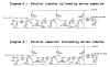
Here are 200mW, 1 watt and 5 watt different RF amps. Each has input and output impedance matching network. Hope these amps are good.

But if I connected these different amps together, may be it is not need to use these network between amps. Because 1st input matching network converts 4K ohms impedance (from oscillator or class A amp) into 10 ohms for Class C input. And at the collector of Class C, there is no impedance change. So I think there is no necessary to use another input matching for next Class C (it is already converted 10 ohm at first). So I used single coupling capacitor- Trimmer and a small inductor.

Only at last I used Output matching network for 50 ohms antenna which converts 10 ohms into 50 ohms. I don't have more idea about such matching network. Am I doing good?
 

Attachments

  • Y.PNG
    Y.PNG
    30.6 KB · Views: 1,178
Last edited:
Suppose the transistor of the middle stage has an input impedance of 3-j3 ohms. Also suppose that the first stage requires a 25 ohm load to achieve the power you want from it. The role of the impedance matching network then is to transform the low input impedance of the middle stage up to the 25 ohm level required by the first stage. In addition, the matching network should absorb (or resonate out) the output capacitance (say -3j ohms for example) of the first stage.

The matching network between the stages would then take the form of a parallel inductor followed by a series capacitor (rather than the series inductor followed by a series capacitor, as you show), the values of which depend on the operating frequency. To prevent the parallel inductor from passing DC through the collector inductor of the first stage, a large value (DC blocking) capacitor must be added between the collector of the first stage and the matching network. Alternatively, a parallel capacitor followed by a series inductor (swap the inductor and capacitor) can be used for the matching network, and the DC blocking capacitor is still needed to prevent DC from forward biasing the middle stage transistor.


The same idea applies to the matching network between the middle and last stages.
 
Last edited:
I knew new thing about impedance matching network, wow!

But I am little confused on your first term "parallel inductor followed by series capacitor" and its DC blocking capacitor, so I made a diagram "A" to show you. Diagram B is alternative suggested by you. Check these please and correct if there are any mistakes.
 

Attachments

  • Corrected impedance.GIF
    Corrected impedance.GIF
    27.6 KB · Views: 520
Hi Willen,

In diagram B, C4 and C6 should be on the left side of the inductors L4 and L7. After that correction, I prefer diagram B since the matching networks are low-pass, tending to suppress harmonics between the stages, though diagram A will work too.

I can't vouch for the values you are using since I don't know the frequency the amp is operating at, or the load impedance that the output of the individual stages, alone, in the diagram in your original post are designed to operate into (assuming they are designed properly).
 
Last edited:
Wow!
I think I corrected now according to your recommendation.

I am laughing at me because I guessed all inductors are not critical hee hee hee so I used values without knowing anything :)

I know L2, L5 and L8 is not more critical but I don't know about others' (inductors and capacitors) value.

Lets say frequency is 100MHz, Q1 is 2N2219A, Q2 is 2N3866 and Q3 is 2sc1971. Input impedance from Class A amp (may be few K ohms?) and output impedance is 1/2 dipole (75 ohms?). Then can you simply assume the values?
 

Attachments

  • impedance Last.png
    impedance Last.png
    14.5 KB · Views: 1,618
Hi Willen, here's how I would go about figuring the values for the interstage matching networks:

1. The first stage is supposed to deliver 200 mW. For simplicity, I'm going to ignore the few pf of transistor output capacitance. You can tweak the values of the inductor and capacitor, once built. When you build it there are going to be parasitic L's and C's anyway to deal with. The load resistor for 200 mW is RL=V^2/(2P), or 12^2/(2*200mW)=360 ohms. I'm going to also assume an input impedance for the following transistor of 5-5j, which is typical. Using an impedance matching program (because who wants to calculate all that by hand?), the values for L and C of the first matching (diagram B) network between the first and middle stages are 37pf and 75 nH.

2. The middle stage is supposed to deliver 1W. The load resistor for 1W is RL=V^2/(2P), or 12^2/(2*1W)=72 ohms. I'm going to again assume an input impedance for the following transistor of 5-5j, which is typical. Using an impedance matching program, the values for L and C of the matching (diagram B) network between the middle and last stages are 81pf and 37 nH

I think too that your blocking capacitors should be higher in value, say 1nF, just so the reactance is low enough not to influence the matching network values significantly.
 
Hi ccurtis,
I am sure you calculation works very good than mine. But I think the inductor is not VERY critical because of its Variable capacitor, isn't it?

You calculated very easily and corrected the values! But you didn't corrected the values of first inductor, last inductor and each collector inductors (as you said these are also critical). Please simply assume the values of these 5 inductors too. I know your assume works very good than mine. Anyway thank you so so much.
 
Hi ccurtis,
I am sure you calculation works very good than mine. But I think the inductor is not VERY critical because of its Variable capacitor, isn't it?.

The variable capacitor will not compensate for an inductor that is not the correct value. The two work together to provide the correct match. If the coil is made with solid wire with air-core, the turns of the coil can easily be moved closer or farther apart to adjust the inductance somewhat.

You calculated very easily and corrected the values! But you didn't corrected the values of first inductor, last inductor and each collector inductors (as you said these are also critical). Please simply assume the values of these 5 inductors too. I know your assume works very good than mine. Anyway thank you so so much.

The self-bias inductors, L2, L5, and L8 are okay at 10uH. The collector chokes (L3, L6, and L9) are okay, maybe bigger than necessary, but better too big than too small. To match the final stage (5W=14.2 ohms) to 75 ohms, L10=47nH and C8=44pF and C7=1nF. On the input side to match to, say, a 2Kohm output from the class-A driver amp, L1=150nH and C2=16pF and C1=1nF.
 
...C7=1nF and C1=1nF.
then should I have to use fixed 1nF disc capacitor instead of trimmer (cause of its high value, there may not available 1nf trimmer). But most of circuits found on internet uses low value trimmer instead of 1nF, um...may be... Are they unnecessary?

Last another problem is still on circuit rest of impedance. The 2nd stage produces 1 Watt, due to this high watt the last stage might be over driven. So I think to add two emitter resistor to 1st and 2nd transistors to low down the power half. Also resistors is good to use to low down the heat of transistors. It's is good if 2nd transistor produce 0.5 to 0.6 watt. It's related to RF power and impedance so I can't even guessed the values of R1 and R2, Can you please?
I think if I used both resistors then again you should have to calculate the values of L and C cause of changing power level. :)

Thank you VERY much!
 

Attachments

  • limit power.png
    limit power.png
    6.6 KB · Views: 366
then should I have to use fixed 1nF disc capacitor instead of trimmer (cause of its high value, there may not available 1nf trimmer). But most of circuits found on internet uses low value trimmer instead of 1nF, um...may be... Are they unnecessary?

The 1nF caps are also blocking caps, like the others, so they are fixed.

Last another problem is still on circuit rest of impedance. The 2nd stage produces 1 Watt, due to this high watt the last stage might be over driven. So I think to add two emitter resistor to 1st and 2nd transistors to low down the power half. Also resistors is good to use to low down the heat of transistors. It's is good if 2nd transistor produce 0.5 to 0.6 watt. It's related to RF power and impedance so I can't even guessed the values of R1 and R2, Can you please?
I think if I used both resistors then again you should have to calculate the values of L and C cause of changing power level. :)

Thank you VERY much!

You're welcome. Rather than add emitter resistors, change the interstage matching networks so they provide a lighter load on the their respective transistor outputs. For example:

1. The first stage is supposed to deliver 100mW (instead of 200 mW). The load resistor for 100 mW is RL=V^2/(2P), or 12^2/(2*100mW)=720 ohms. Still assuming an input impedance for the following transistor of 5-5j, which is typical. Using an impedance matching program, the values for L and C of the first matching network between the first and middle stages are 27pf and 87 nH.

2. The middle stage is supposed to deliver 0.5W (instead of 1W). The load resistor for 0.5W is RL=V^2/(2P), or 12^2/(2*0.5W)=144 ohms. Using an impedance matching program, the values for L and C of the matching network between the middle and last stages are 58pf and 34 nH.
 
Last edited:
Wow! :eek:
I REALLY did not know that impedance matching network plays such huge role in power dissipation of transistor!!!

...and 1st L,C (input) and Last L,C (output) will be same value as u said before i think. Because there nothing has been changed.

How simply you calculated! Wow! Can you give me the link of the software (you are using) to find out the values of L and C please! Thank you again

Yes, those L's and C's will stay the same. I used this calculator, mostly the network on the right side of the topmost line.

https://home.sandiego.edu/~ekim/e194rfs01/jwmatcher/matcher2.html
 
I knew each impedance matching inductor is VERY critical and can't adjust it via trimmer. Then I should have to wind the coil very accurately, accurate diameter (radius X 2), hight and turns. It needs great skill hm...! Hope this type of calculator plays great role for me to make accurate inductors-
check once please
http://www.pulsedpower.net/applets/electromagnetics/rfcoil/rfcoil.html

There I found new thing- "Note that L doesn't depend on wire diameter!" wow! Then I can use 18 SWG or 24 SWG any wire! Isn't it? Hope I can do!

Perhaps L doesn't depend on the wire diameter, but how many turns you can make in a given length and spacing between the turns does depend on the wire diameter! And smaller diameter wire has higher resistance for less Q.

The formula that is generally used to design practical single layer RF (to UHF) air-core inductors is accurate to within 1 percent if l > 0.67r :

Inductance (L in uH) = (0.394r[SUP]2[/SUP]N[SUP]2[/SUP])/(9r+10l)

Where r=the coil radius in cm
l=the coil length in cm
N=number of turns

You can compare that to the calculator at the link you gave. And, again, you can tweak the inductance of the coil to some extent by adjusting the spacing between the turns after the coil is mounted. An entire outside turn can be bent completely over if need be. Back in the day, tweaking coil and caps was a common final test procedure.
 
Last edited:
Perhaps L doesn't depend on the wire diameter, but how many turns you can make in a given length and spacing between the turns does depend on the wire diameter! And smaller diameter wire has higher resistance for less Q.
Thicker wire= high Q?

The formula that is generally used to design practical single layer RF (to UHF) air-core inductors is accurate to within 1 percent if l > 0.67r :

I cannot understand l > 0.67r : , what that mean please!


You can compare that to the calculator at the link you gave.
The different between your and his formula is- your has '0.394' multiplied with 'R^2 N^2'. I don't know why 0.394 is multiplied here.
 
Last edited:
Thicker wire= high Q?

Yes, because the resistance is lower.

I cannot understand l > 0.67r : , what that mean please!

It means that the length of the coil is greater than 0.67 times the radius of the turns.

The different between your and his formula is- your has '0.394' multiplied with 'R^2 N^2'. I don't know why 0.394 is multiplied here.

The formula I posted uses the centimeter as the unit for distance, instead of the inch.
 
Last edited:
To match the final stage.......
It's interesting!

One thing I want to ask, audioguru designed a basic Tx without impedance matching. His last Class A amp has very high impedance but using very low impedance whip antenna. If I simply added a matching network (L and C) on this, may be output level will increase. Now he is transmitting 23mW from +9V (It's transmitting 2 KM on very sensitive Rx).

This is the circuit:
www.electro-tech-online.com/attachments/fm-transmitter-tuning-png.62593/ (here, as you said lets say C14 is 1nF DC blocking capacitor instead of 22pf.)


How to add matching (LC) network here? Like 1st stage or like last stage (previous attached). Can you simply assume schematics and value of L and C please. (output impedance is 75 ohm dipole). Sorry if i am irritating you.

Similar to the class C stages where I gave the formula for calculating the load resistor to extract a desired amount of power from the transistor output, in the audioguru circuit a load resistor of about 200 ohms is required to extract the maximum power of ~23mW (assuming 400mV peak voltage drive level before the 30pF base capacitor). In the class C stages the collector choke is also a high impedance, just like the resonant tank of the audioguru output stage. The lower the load resistor (to a point) the more power is extracted from the stage. You can calculate the L/C matching network to get from 200 ohms to 75 ohms. On the matching calculator, in the upper right hand circuit, the L=154nH and the C=10pF. The existing series capacitor would be a large DC blocking capacitor.

As a side note, that 47K bias resistor could be trimmed for the particular output transistor and the drive level from the previous stage since some power can be wasted in excessive DC quiescent current through the tank inductor when all that is useful is the change of current through it. It could be trimmed so that the collector current drops down to near zero at the lower peaks. Depending on the particular transistor gain and drive level, that resistor could possibly be 3 times or more greater than 47K, saving some battery power.
 
I changed a few capacitor values for higher output power and lower harmonics levels. You can see that the output makes a very good sinewave.
The output power is 282mW in my simulation. If the value of C7 is increased then the output level drops and there are obvious harmonics.
The value of C6 can be from 100pF to 300pF without changing the output. If C2 is increased to 10pF then the output level is a little higher but the harmonics become obvious.
 

Attachments

  • FM transmitter tweaked.png
    FM transmitter tweaked.png
    29.8 KB · Views: 365
- Hi ccurtis,
Which one is best among them? Are there any huge difference?

- Hi audioguru,
I think 23mW is produced without impedance matching. But if I used this impedance, Can't I get more power than 23mW?
 

Attachments

  • MOD4.PNG
    MOD4.PNG
    5.9 KB · Views: 343
Status
Not open for further replies.

Latest threads

Back
Top