Continue to Site

Welcome to our site!

Electro Tech is an online community (with over 170,000 members) who enjoy talking about and building electronic circuits, projects and gadgets. To participate you need to register. Registration is free. Click here to register now.

  • Welcome to our site! Electro Tech is an online community (with over 170,000 members) who enjoy talking about and building electronic circuits, projects and gadgets. To participate you need to register. Registration is free. Click here to register now.

I'm about to throw my PIC through the wall HELP!!!!!!

Status
Not open for further replies.

duct996

New Member
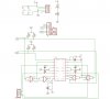
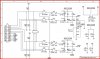
I'm new at this but I can build simple circuits and other stuff, but I can not seem to find anyone to help me figure this out. I have 2 circuit designs for the SN754410 H-bridge driver. Both uses a SN74HC00 chip as well. One has 2 wires going into the the A and B side of the SN74HCoo and one only uses 1 wire to both A and B. I am using the Mechatronics demo board with the pic 16f690 chip. Now I am using the demo project #9 for the program. I have built the motor driver from the freeduino schematics that is in green. The 4 wires comming from the 16f690 are 2 positives and 2 negative wires about 5V. and when you hit the switch 2 it changes the polarities on all 4 wires. HOW DO I HOOK IT UP TO ONE OF THESE SCHEMATICS!!! Which one is the right one?? PLEASE SOMEONE HELP. I assume that once I can get this to work then all I would have to do is change the program alittle to change the direction of the motor with a senor or bump switch.
 

Attachments

  • freeduino_motor_schematics_L.jpg
    freeduino_motor_schematics_L.jpg
    132 KB · Views: 157
  • Picdesign motor controller.JPG
    Picdesign motor controller.JPG
    80.6 KB · Views: 146
ok but thats a different way altogether. I'm only using 4 wires to the sn754410 and if it works on the demo board that way why can't I do it off the board?? Also could you tell me why the sn74hcoo is used sometimes but not always like your design? Which is better?

Now that I Look alittle closer at your schematic can I set it up with just the 1a and 2a and without the pwm? Would that give me my Positive and negative? Dumb question I'm sure.
 
Thanks but I'm still confused. Here is the board that I have. Hopefully you can see the pins that are connected. I would like to use whats there except instead of connecting it to J1 I would like to connect it to the freeduino board (schematic below), because this is what I have. Could you tell me step by step how to do it? Like, take ccp1 and connect it to pin (blank) on the sn74hc00 chip. Then take C2out to pin (blank) and so on? I would really like to do it this way so I don't have to change any programming. THanks
 
Hey Bill I made your schematic on a breadboard and guess what it worked. I guess I must have put my other board together wrong or something. Either way Now I have something that works and with the PWM. Thanks so much I know it must be hard teaching Monkeys to talk. LOL.
 
LOL, glad it worked. The 754410 is really easy to use and great for small motors. Remember your motors get about 1.4V less then the motor supply voltage.
 
Status
Not open for further replies.

New Articles From Microcontroller Tips

Back
Top