Electro Tech is an online community (with over 170,000 members) who enjoy talking about and building electronic circuits, projects and gadgets. To participate you need to register. Registration is free. Click here to register now.
Welcome to our site! Electro Tech is an online community (with over 170,000 members) who enjoy talking about and building electronic circuits, projects and gadgets. To participate you need to register. Registration is free. Click here to register now.
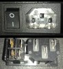
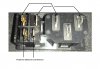
Could someone please give me info on how these are wired? I know the pin outs for the power side, not sure how the switch is wired. Attached image to post.
In the US, I would use the switch to break the Line (black) side. Since you didn't put in a country when you registered, I can not suggest what you would do...
I believe the switch you have switches both the line and neutral conductors, You may need to use an ohmeter to determine how the 4 connections are switched.
On the solder side of your switched receptical, connect a short black wire jumper from L to one side of the switch. Connect the output of the switch to the Line input of the power supply or whatever is in the box to which the receptical is mounted on.Even if the switch is a double pole switch, I would only break the Black Line wire side; not the Neutral.
You should also put a fuse in the long black wire between the switch and whatever load is in the box.
This site uses cookies to help personalise content, tailor your experience and to keep you logged in if you register.
By continuing to use this site, you are consenting to our use of cookies.