Continue to Site

Welcome to our site!

Electro Tech is an online community (with over 170,000 members) who enjoy talking about and building electronic circuits, projects and gadgets. To participate you need to register. Registration is free. Click here to register now.

  • Welcome to our site! Electro Tech is an online community (with over 170,000 members) who enjoy talking about and building electronic circuits, projects and gadgets. To participate you need to register. Registration is free. Click here to register now.

Idea for fixing audio amp with output fet

Status
Not open for further replies.

dimpa77

New Member
Hi, I have amp which burned the output mosfet ( I don’t have diagram) only some ideas , anyway , if I put new mosfets, they will burn with fuses . Please take a look at the pictures, maybe you have more experience then me , thanks
 

Attachments

  • image.jpg
    image.jpg
    1.3 MB · Views: 217
  • 308E62EB-7793-4EED-9A1E-9B4FAA4CD701.jpeg
    308E62EB-7793-4EED-9A1E-9B4FAA4CD701.jpeg
    2 MB · Views: 211
I think you are missing quite a few components from the diagram, but if you have all the transistors shown, the implication is it's a fault in one of the drivers, the BC550/560 ?

What amp is it? Schematics are available online for many types.
 
Thank you for reply , yes , you are right, I have tried to find out the schematic ( but no luck , it is German horn speaker amp . Advantage Acoustic, Also I have checked both translations bc550 and bc560 , they works
 
OK, it's an Avantgarde Acoustics PA101 board.

The centre transistor near the pot is missing from your diagram - that circuit sets the bias "standing current" in the output stage and if anything around there is faulty it could cause a very high bias current through the power stage and cook things...

Through-PCB view here:
**broken link removed**

I've not managed to find a proper schematic yet - but more info and photos in this thread:

Interestingly, not all the photos show the centre transistor fitted? I wonder if it is under the PCB rather than fitted to the heatsink.


I'd be tempted to run the amp with a large resistor (or filament lamp) in series with each power connection, so it cannot draw enough current to damage thing but has stable voltages so you can take measurements.
 
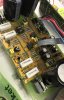
Thank you for info , the missing transistor is bc550 ( I checked it , good. also i have checked resistor and film capacitor) I inspected board on some shorted ( i did not find any )
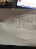
I have tied to find a schematic , - no luck
When I remove ic 5534 from the board and remove fuses ( I was able to adjust voltage on the gates ( but it was high (4,5V on IRF 640 and 4.7 V on irf 9450 but when I put ic 5534 back to board ---4,7 and 11V
so I put another chip 5534 - no luck
The board does not have any elements on another side .
Question , Could transistors bc550 and bc560 are very close ? or should I make mosfets match
 
remove the FETS, and connect a 50k resistor from the positive side gate resistor to the positive side source resistor, and likewise for the negative side. this will provide a feedback path so the amp doesn't latch to a rail during testing. turn on the amp and measure the voltage between the positive side gate connection and the negative side gate connection. you should have between 4 and 8 volts across the gate connections. more than that, and the output devices will draw too much current. with the voltmeter still connected operate the potentiometer and insure the voltage changes, and you should be able to turn it down to 2V or so

with the 50k resistors in circuit, you should be able to feed in a signal, and get some signal appearing on the output (do not connect a load to the amp) if everything else is working ok.
 
Last edited:
Status
Not open for further replies.

Latest threads

New Articles From Microcontroller Tips

Back
Top