electronicsfreak
Member
Hello. I hate to make another help post, but I am looking for input for this particular project.
I am looking for any suggestions as to what might allow my programmer to program a PIC12F675 in circuit. After already building the board and simply splicing wire leads in to the necessary pins on from the IC socket I have found that attempting to program the PIC fails. I know that there is one/a few things on my particular circuit that may be preventing this thing from being programmed, and I thought I may as well see if anyone has any insight.
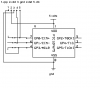
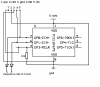
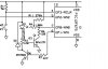
At the moment when I am trying to program, MCLR/Vpp is pulled up using a 56Ω resistor, data is pulled up through a resistance near 360kΩ, clock is tied in with the base of a 2N3904 transistor through a 4700Ω resistor, Vdd is at 5V, and Vss is at 0V.
I know that what is hindering my programmer may be fairly obvious, but I am only a mere hobbyist for the moment.
Any suggestions?
I am looking for any suggestions as to what might allow my programmer to program a PIC12F675 in circuit. After already building the board and simply splicing wire leads in to the necessary pins on from the IC socket I have found that attempting to program the PIC fails. I know that there is one/a few things on my particular circuit that may be preventing this thing from being programmed, and I thought I may as well see if anyone has any insight.
At the moment when I am trying to program, MCLR/Vpp is pulled up using a 56Ω resistor, data is pulled up through a resistance near 360kΩ, clock is tied in with the base of a 2N3904 transistor through a 4700Ω resistor, Vdd is at 5V, and Vss is at 0V.
I know that what is hindering my programmer may be fairly obvious, but I am only a mere hobbyist for the moment.
Any suggestions?