Continue to Site

Welcome to our site!

Electro Tech is an online community (with over 170,000 members) who enjoy talking about and building electronic circuits, projects and gadgets. To participate you need to register. Registration is free. Click here to register now.

  • Welcome to our site! Electro Tech is an online community (with over 170,000 members) who enjoy talking about and building electronic circuits, projects and gadgets. To participate you need to register. Registration is free. Click here to register now.

I would like to build a pulse generator that can be used as a single shot when power is on

Status
Not open for further replies.

milkoni

Member
Hi,
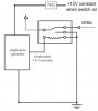
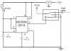
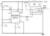
I would like to build a pulse generator that can be used as a single shot between 1 and 5 seconds when power is on and the power is permanent. In first file is principal schematics of my idea. In second is my try with 555 timer. But it doesn't work.

Thanks in advance!
 

Attachments

  • fuel_level1.jpg
    fuel_level1.jpg
    13.4 KB · Views: 186
  • fuel_level.jpg
    fuel_level.jpg
    19.6 KB · Views: 205
Welcome to ETO!
Try googling '555 monostable schematic'.
 
Your drawings won't work as it shows 12 volts going into a 7812 regulator. The 78xx series have a minimum 2 volt dropout voltage so a 7812 needs a minimum of 14 volts on the input. That is one problem I see.

Thanks!
I tried but it doesn't work like I want.

You pretty much describe a "One-Shot" but what exactly are you wanting the circuit to do, exactly in detail?

Ron
 
Your drawings won't work as it shows 12 volts going into a 7812 regulator. The 78xx series have a minimum 2 volt dropout voltage so a 7812 needs a minimum of 14 volts on the input. That is one problem I see.


You pretty much describe a "One-Shot" but what exactly are you wanting the circuit to do, exactly in detail?

Ron
In detail - When I turn on the power of my car, I would like to cut off the signal from fuel level sensor to ECU for 1 to 5 seconds with a relay (I don't know how long time exactly - I'll experiment with this). After the signal must be restored. The input signal - 12V remains until I turn of the car - it's constant.
 
When you say 'it won't work', exactly what doesn't happen? Is there 12V at pins 4 and 8 of the 555? Does the relay click and energise?
One thing missing is a back-emf spike suppression diode across the relay coil. Without that the 555 will quickly die.
You really should have something like a 1k resistor for discharging C1 via pin 7. Without that, pin 7 could crowbar the 12V supply if the 47k trimmer were set at a low value inadvertently.
When I said it doesn't work" I meant that it generate more than one pulse when I turn the power on.
 
That could be due to interference caused by the back-emf voltage spike.
 
When I said it doesn't work" I meant that it generate more than one pulse when I turn the power on.
That's because you have pin 7 connected; disconnect it (it is making the system into an oscillator).

For reliability, you may wish to add:
* a diode across the relay coil (anode to pin 1, cathode to pin 3) for back EMF when the relay is switched off.
* a capacitor across the power supply before the 7812 >=100nF and one after the 7812 of >=2uF, for stability of the 7812 regulator.

If you don't want to have to wait for the 100uF to discharge slowly on power off, then connect a diode across the 47k pot. (anode to pins 2/6, cathode to pin 8).
 
Thanks a lot!
I tested it in Electronics Workbench - perfect. Exactly that I want.
Tomorrow I'm going to make a real project.
Thank you for help again!
 
Hi again!
I decided to modify my pulse generator. I've changed to timer 555 to Astable mode - fuel_level_pulse.pdf.
My idea is to use in this circuit a MOSFET instead of relay - fuel_level_pulse_t.pdf.
In the second circuit with a MOSFET I would like to add an additional parallel resistance to Fuel gauge through it. This will provoke the computer of car to recalculate the remaining fuel in reservoir.
Is the second circuit will work as I think?
 

Attachments

  • fuel_level_pulse.pdf
    66.4 KB · Views: 213
  • fuel_level_pulse_t.pdf
    64.2 KB · Views: 343
Hang on a minuet, why do you want to do this? Messing with the fuel system using a part that isnt speced for automotive use is not a great idea, I dont mean to be funny honestly but think about this first. If the circuit goes wrong be aware you could suddenly loose power at speed while over taking, its really not a great idea to mess with car stuff like this unless you really know what your doing. I am not being a PITA but I did want to point out a potential safety issue, This public safety broadcast is now over.
 
I do this because when I'm driving on LPG, the computer continue to decrease remaining fuel (petrol) in tank. Currently I'm using the circuit with relay in my car. I would like to know - may I replace the relay with MOSFET and it is reliable?
 
In detail - When I turn on the power of my car, I would like to cut off the signal from fuel level sensor to ECU
I am not sure how cutting off the fuel sensor will do what you want? If the ECU deducts fuel when no fuel is being used then killing the signal isnt going to help?

At least from a safety point I cant see too many issues as long as you dont try and switch while driving, thanks for clearing that up. I didnt want to sound like the fun police but it sounded more dangerous than it turned out to be :D
Cutting the signal was an old idea. With this circuit I take the signal from Fuel switch (+12V) to power my circuit (only when engine operate on LPG).
As you can see in first file (this circuit I use now) - when the engine switches to LPG the timer redirects the signal through a resistor 100 Ohms for a about 10-12 seconds (this value means for ECU about a half tank fuel for my car). The ECU detects a change in level and recalculate remaining fuel in tank with a new value. After 10-12 seconds, the timer restores the original signal from tank. The ECU calculates again the real remaining fuel. Then every 24-25 minutes - when I'm on the way, the timer circuit repeats this. Using this circuit, I always have actual remaining fuel in tank.
 
Last edited:
Status
Not open for further replies.

Latest threads

Back
Top