Continue to Site

Welcome to our site!

Electro Tech is an online community (with over 170,000 members) who enjoy talking about and building electronic circuits, projects and gadgets. To participate you need to register. Registration is free. Click here to register now.

  • Welcome to our site! Electro Tech is an online community (with over 170,000 members) who enjoy talking about and building electronic circuits, projects and gadgets. To participate you need to register. Registration is free. Click here to register now.

I want to make of my own smps but.. I need help for idea.

Status
Not open for further replies.

vedo35

Member
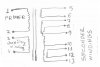
Guys this of my smps transformer you are seeing pinouts. I want to use SG6841 smps controller.
My question is at secondary side to which pinout(s ) do i have to connect ground? There are 9 pinouts . if works normal probably i will get at least 6- or 7 outs. I checked a lot of scheme with SG6841 and also own datasheet but between windings some scheme using zener diots and in own datasheet scheme there are only one winding. But mine there are 4 windings with common used one total 5 windings. Can you help me for secondary side ground and between winding connection reletions?
Thanks for all helpful answers or schemes.
 

Attachments

  • Image (9).jpg
    Image (9).jpg
    56.2 KB · Views: 738
Do you have a data sheet for the transformer?
What output voltages do you want?
What input voltage?
There are many different ways to use this transformer, depending on what you want.
 
Thanks for answer unfortunately not. I got this transformer years ago from i think dvd player or vcr player. I wanted use of this trans formet . probably there are 3.3v, 5v, 12v, and 23 or 24volt outs. I dont have problem with primer and auxiliary side. Axu giving enough voltage for sg6841. I already made pcb with eagleand even made worked only tl431 suplay side other windings giving abnormal voltages and if you give load smps outs going to zere and coming back again. I did all options nothing changed. Only explode one time mosfet. So my problem one of this windings will be grounded and between windings i have to use zener or so.or something like that. I need for secondaty side.
 
It is important to find out what your transformer will do.
You could connect the SG6841 and see what happens.
OR
You could connect a signal generator to the primary and look at the secondaries and see what the turn ratio is and the phase.
If we knew that, then we could look at the many combinations available. (Windings can add.)
There are different ways of using diodes. Using a center tapped winding you could get +5V, +5&-5V, +10V, +10v&+5, -5v, -10v, -10&-5. With a little thing I could make other voltages.
 
himmm signal genetator i dont have. but i made a primitive pcb for just experiment
and working or not. i used first normal fast diods later i used double
dios wasnt giving stable voltage. i thought i made mistake with gnd connections.
 
Status
Not open for further replies.

New Articles From Microcontroller Tips

Back
Top