Electro Tech is an online community (with over 170,000 members) who enjoy talking about and building electronic circuits, projects and gadgets. To participate you need to register. Registration is free. Click here to register now.
Welcome to our site! Electro Tech is an online community (with over 170,000 members) who enjoy talking about and building electronic circuits, projects and gadgets. To participate you need to register. Registration is free. Click here to register now.
wut r u trying 2 switch on n off? Cuz if it's something that needs to stay on after current is gone, something that a simple transistor can't do, you might try a SCR. Even if the gate current is gone, it still lets current flow through it until the current flowing through it shuts off. Then it resets itself. Someone correct me if I'm wrong, but I think this is how an SCR works.
I need something with EXACTLY the same properties as a relay. When power flows to A, power goes from B to C, and when there ain't any power going to A, no power will go from B to C either. Think you get the point.
Its depended in what current\voltage you need to switch on\off and in what frequency.
You can use a simple transistor or MOSFET transistor for switching.
I also find out recently a very nice IC (LCA110) by "Clare", they are calling it "MOSFET Relay".
Basicly its a very nice optcoupler that can manage 350V/120mA in its load and works like a true relay.
The major difference between a relay and a solid state relay is that the solid state device has 1 or 2 volts drop across it and it will get hot if not heat sunk when carrying high current.
Lac, a 4066 cmos quad bilateral switch may be what you are after.
It's a chip with 4 switches, that will work similar to 4 indipendent relays.( if you wire it up properly).
no, the resistors have such a high resistance so as to keep it deep into saturation. no matter what the input voltage the circuit will act as a switch. but this is not the kind of switch u need. this is a digital switch. u need an analogue switch. a solid state relay or an SCR should be your choice. what are your current requirements. and when u say simple 12VDC what do u mean. is that the voltage that is going to trigger the switch or is it the voltage that is going to be triggered.
I need something with EXACTLY the same properties as a relay. When power flows to A, power goes from B to C, and when there ain't any power going to A, no power will go from B to C either. Think you get the point.
The only thing 'exactly like a relay' is a relay! - you don't give anywhere near enough information to make informed suggestions. For example:
What are you switching?.
What current are you switching?.
What voltage are you switching?.
Is it AC or DC?.
What is the switching signal?.
How fast does it need to switch, and why?.
How often does it need to switch?.
To produce a solid state circuit to replace a relay we need to know all these, and possibly a few more? - as a relay is simply a mechanical switch, it's far easier.
I'm having this digital-clock-circuit that will usally be plugged into the wall, but when I disconnect it from the wall (to move it to a new location or something like that) I want the clock to keep on running (so the time is always ticking, and I don't need to set the time each time I have disconnected it from the wall)
To be able to do this I need some kind of backup power, in this case a 7.2V battery. So what I want to do, is that when the power from the wall is disconnected the battery will kick in. I have tried this with a relay, but the time it takes to switch it from "wall-power" to "battery-power" is much to long, since this is a digital clock the time will be EXACT at all times, and therefore I can't allow it to be a little delay when the clock is disconnected and/or disconnected
So what I simply need is a way to switch between the two power sources, in no time, dependent if power is coming from the wall's 12VDC or not.
The freq. that it will be switching is dependent on how often it will be moved around my house, and I don't think that will be more often than mostly once a week.
Cheers! I Hope I made myself a little more intelligible now :wink: .
Lac
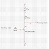
All you need is two rectifiers, wired as an OR gate like the diagram attached. You could even probably use just one rectifier, on the battery side - the bridge recifier on the mains transformer would work as the other rectifier.
hmm..but wouldn't that constantly tap power from the battery, and double the current when it is connected to the wall? I'm surely wrong, but I have fairly ever used a rectifier.
hmm..but wouldn't that constantly tap power from the battery, and double the current when it is connected to the wall? I'm surely wrong, but I have fairly ever used a rectifier.
No, the mains supply will be a higher voltage than the battery (you should make sure it is!) - so the rectifer from the mains supply will be forward biased, passing power to the clock/radio, and the rectifier from the battery will be reverse biased - passing no current. When you unplug the mains the incoming supply will drop, and accordingly the junction of the two diodes will drop as well - as soon as it gets low enough the recifier from the battery will become forward biased and start to supply power to the clock/radio.
It's a standard technique, it's used in loads of commercial applications - including clock/radios which have battery backup!.
hmm. I tested the thing with two diodes, but it look like it won't work :? I'm using two standard 50V rectifier diodes. connected with the white band to - . Any suggestion what could be wrong?
It works fine when the bat is connected, but when i also connect the wall, the power going from the bat won't stop. so what I get is a double current.
Cheers!
Lac.
EDIT: whoops! meant - instead of + , fixed now. The above is right.
This site uses cookies to help personalise content, tailor your experience and to keep you logged in if you register.
By continuing to use this site, you are consenting to our use of cookies.