Okie, heres the main story,
my cable modem occasionally stops responding and requires a power off- power-on reset, no other ways, (does not happens often, but it does)
I'm heading to aussy for study 3 yrs, but i intend to keep my home system, online for this period, so i can access it and webcam to my folks at home who are computer idiots..,
but this requires my net connection to be stable
so i came up with this idea to reset my modem
i bought a digital timer switch - programable
it has a back up battery (but since this entire unit is kinda of "MADE in CHINA"), i doubt the button battery is even rechargeble, thus it requires replacing say every 100 hours..( this is only if the battery is being utilised)
the guy sold it says thats roughly a replacement every 1 yr or so..
but i'm not about to find out the hard way,
the battery is 1.2v button battery
i bought a variable output transformer from 1.5 v to 12 v
since its another stupid china brand, i measured and found out, that
it does not provide 1.5 instead it gives from 3.5v to 17 v (WTH ?!)
anyway, i switched it to the lowest possible, its still 3.5v
so i created and design a simple circuit which now i may need some help
a simple diagram first for those who understand it,
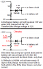
VCC 3.5 --- R1 --- R2 --- GND
since i rumaged thru what ever resistors i had left from other projects
i manage to find,
4x 1k ohm resistors
2x 2 k ohm resisters
connected them pareller in this order
R1 = 3x 1k ohm in parallel, this gives me about 333.33 ohms
R2 = 2x 2k ohm and 1x 1k ohm in parallel, this gives me about 500 to 600 ohms
i tested the voltage accross this circuit
@ R1 i get 1.3 Vs (just nice)
@ R2 i get 2.0 Vs (useless at the moment but may come in handy to charge my batteries)
now after i designed tested this circuit, it seems to work fine and perfectly
until i suddenly went back to square one. WHAT if my power fails ?
my computers are automated and i have a modem attached i can boot it up with a phone call any time, but the modem.. its stucked well
case1, power fails, modem reboots, system reboots (perfect)
case2, power fails, modem reboots, system reboots, timer switch reset (since power was based on a transformer, if power failed, transformer loses power, the programmed settings on the timer switch would be lost (bad stuff) thus if power doesn't fail very often, i'm stucked with a dead modem
so i added a new circuit to this
VCC - R1 - R2 - GND
Between R1 terminals
1 set connects to the timer switch to power it so i dun have to replace the battery,
the other set connects to a normal ni-mh rechargerable battery, lol by sony if you would..
now the question is will this circuit works ?
will 1.3 v shared between the timer switch, also be sufficeient to recharge this battery ?
2ndly, in the event of a power fail, in that configuration, won't the battery be drained faster since it now powers, both R1 circuit (simple power dissipation) and the timer switch itself....
or should i switch to the other side of the circuit and have the R2 parallel the batt and the timer switch, but then this would also up the power dissapation since there are higher resistor values ?
lastly, even tho in this circuit i'm supposed to use lower resistor values as this restricts quite a number of current, thus weaken the entire cicuit and slowed down the normal recharge time of the battery, (but ths produces less heat (safety 1 i guess), and will such constant recharging, casue the battery to leak ? or be damage or worse expldoes....
thanks in advance
my cable modem occasionally stops responding and requires a power off- power-on reset, no other ways, (does not happens often, but it does)
I'm heading to aussy for study 3 yrs, but i intend to keep my home system, online for this period, so i can access it and webcam to my folks at home who are computer idiots..,
but this requires my net connection to be stable
so i came up with this idea to reset my modem
i bought a digital timer switch - programable
it has a back up battery (but since this entire unit is kinda of "MADE in CHINA"), i doubt the button battery is even rechargeble, thus it requires replacing say every 100 hours..( this is only if the battery is being utilised)
the guy sold it says thats roughly a replacement every 1 yr or so..
but i'm not about to find out the hard way,
the battery is 1.2v button battery
i bought a variable output transformer from 1.5 v to 12 v
since its another stupid china brand, i measured and found out, that
it does not provide 1.5 instead it gives from 3.5v to 17 v (WTH ?!)
anyway, i switched it to the lowest possible, its still 3.5v
so i created and design a simple circuit which now i may need some help
a simple diagram first for those who understand it,
VCC 3.5 --- R1 --- R2 --- GND
since i rumaged thru what ever resistors i had left from other projects
i manage to find,
4x 1k ohm resistors
2x 2 k ohm resisters
connected them pareller in this order
R1 = 3x 1k ohm in parallel, this gives me about 333.33 ohms
R2 = 2x 2k ohm and 1x 1k ohm in parallel, this gives me about 500 to 600 ohms
i tested the voltage accross this circuit
@ R1 i get 1.3 Vs (just nice)
@ R2 i get 2.0 Vs (useless at the moment but may come in handy to charge my batteries)
now after i designed tested this circuit, it seems to work fine and perfectly
until i suddenly went back to square one. WHAT if my power fails ?
my computers are automated and i have a modem attached i can boot it up with a phone call any time, but the modem.. its stucked well
case1, power fails, modem reboots, system reboots (perfect)
case2, power fails, modem reboots, system reboots, timer switch reset (since power was based on a transformer, if power failed, transformer loses power, the programmed settings on the timer switch would be lost (bad stuff) thus if power doesn't fail very often, i'm stucked with a dead modem
so i added a new circuit to this
VCC - R1 - R2 - GND
Between R1 terminals
1 set connects to the timer switch to power it so i dun have to replace the battery,
the other set connects to a normal ni-mh rechargerable battery, lol by sony if you would..
now the question is will this circuit works ?
will 1.3 v shared between the timer switch, also be sufficeient to recharge this battery ?
2ndly, in the event of a power fail, in that configuration, won't the battery be drained faster since it now powers, both R1 circuit (simple power dissipation) and the timer switch itself....
or should i switch to the other side of the circuit and have the R2 parallel the batt and the timer switch, but then this would also up the power dissapation since there are higher resistor values ?
lastly, even tho in this circuit i'm supposed to use lower resistor values as this restricts quite a number of current, thus weaken the entire cicuit and slowed down the normal recharge time of the battery, (but ths produces less heat (safety 1 i guess), and will such constant recharging, casue the battery to leak ? or be damage or worse expldoes....
thanks in advance