Electro Tech is an online community (with over 170,000 members) who enjoy talking about and building electronic circuits, projects and gadgets. To participate you need to register. Registration is free. Click here to register now.
Welcome to our site! Electro Tech is an online community (with over 170,000 members) who enjoy talking about and building electronic circuits, projects and gadgets. To participate you need to register. Registration is free. Click here to register now.
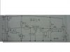
It looks like a simple and very old kit.
The IC has a part number that is not used by any semiconductor manufacturer so it is a special number used only by the kit maker. We don't know what it is for.
The ultrasonic transducers do not have a part number for us to see which type and which frequency they are used for.
They're ultrasonic microphones so it can't be a stereo amplfier, besides the schematic doesn't look like a stero amplifier.
T3 is a common emitter amplifier with U2 at its input, not output, which suggests that U2 is a microphone, not a speaker.
U1 is connected to the output of another common emitter amplifier (T2) which suggests it's a speaker but the text says it's a microphone.
The IC could be anything, I couldn't find the datasheet. How does it get its power supply? Via R2, R7 and P1? That doesn't make much sense, there again we don't know what the IC is.
hmm the ic is TIP 41B while the transducer is those 2 microphones . 1 of them is transmitting and receiving ..! but i don't know which want is transmitting and receiving..
A TIP41B is a power NPN transistor, not an IC. It is shown connected wrong. I think it is supposed to turn off the LED when an ultrasonic signal is received. It does not need to be a big power transistor since an ordinary little transistor can do the same thing.
The entire schematic is drawn backwards since the input is on the right side instead of being on the left side.
I don't know why it has an ultrasonic microphone that is amplified then the same signal drives an ultrasonic speaker.
The value for resistor R6 appears to be too low.
I cropped the schematic since it was too long and I turned around Q4.
This site uses cookies to help personalise content, tailor your experience and to keep you logged in if you register.
By continuing to use this site, you are consenting to our use of cookies.