Electro Tech is an online community (with over 170,000 members) who enjoy talking about and building electronic circuits, projects and gadgets. To participate you need to register. Registration is free. Click here to register now.
Welcome to our site! Electro Tech is an online community (with over 170,000 members) who enjoy talking about and building electronic circuits, projects and gadgets. To participate you need to register. Registration is free. Click here to register now.
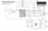
This is rather confusing?, because you ask about a DC motor, and your diagram says 'stepper motor'. But I'm presuming you mean DC motor, as a stepper can't possibly carry on rotating, as they don't really 'rotate'.
OK - I don't see why you mention the diodes?, they are there simply to prevent the back EMF from damaging the transistors, not to try and stop the motor. All your circuit is doing is removing the power to the motor, and it will simply freewheel to a halt - as any DC motor will!.
If you want it to stop more quickly you can 'short' it out, this provides substantial braking to the motor. In order to do this, you need to turn a pair of transistors ON - I would suggest the bottom two are best, make 100% sure the top two are OFF, or you will short the supply out. This should make it stop a lot faster!.
Turning the bottom two transistors ON (Q2 and Q4) shorts the motor out, this makes it stop a lot faster - it's a common and well known technique.
Some motor drive IC's even have an extra input pin which does just that, often labelled 'brake' or something similar.
If you want to stop the motor even more quickly, give it a short pulse in reverse - you need to time the pulse accurately in order to stop the motor as quickly as possible, without going backwards.
Do you mean to connect between a PIC and the stepper motor? (a simple driver), or one that does the complete stepping sequence for you?.
If you're using a PIC it's easy to generate the steps in software, and use simple driver transistors (or a ULN type driver chip) to feed the motor. It also give you far more control over the motor.
This site uses cookies to help personalise content, tailor your experience and to keep you logged in if you register.
By continuing to use this site, you are consenting to our use of cookies.