Continue to Site

Welcome to our site!

Electro Tech is an online community (with over 170,000 members) who enjoy talking about and building electronic circuits, projects and gadgets. To participate you need to register. Registration is free. Click here to register now.

  • Welcome to our site! Electro Tech is an online community (with over 170,000 members) who enjoy talking about and building electronic circuits, projects and gadgets. To participate you need to register. Registration is free. Click here to register now.

I fried my sensor; help identifying surface mount capacitor

Status
Not open for further replies.

211

Member
I have one of these PIRs that I think I let the smoke out of. I'm pretty sure either the power or signal wires shorted to ground. At any rate, it stopped working and I noticed the exposed leads were touching and one of the SM capacitors looked damaged.

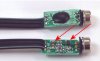
Have a look at the attached image pulled off the PDF. The two arrows indicate the capacitors although the photo differs from what is acutally on the board.
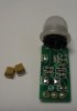
Here's where my delema lies. I removed both of the caps in order to test them, hoping only the damaged 'looking' cap was bad and I could pull a value off the 'good' one. Problem is they both read Open when using my Fluke 87 in capacitor mode.

Now it's possible both of them could be bad but before I go replacing components it's necessary to know what the values of these are and if I'm even testing them correctly.
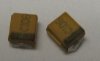
On the top of the cap it says "C106", has a thin black line on one side indicating it's polarity sensitive.
Tell me if I'm right or wrong, but from what I've gathered a C106 capacitor is 10uf...

Also is it necessary to remove the cap from the board when testing, like you would a resistor? Reason being there's another, much smaller cap, on the board that tests open also but I did not remove it. The other caps all read a value which I assume means they're okay.
 

Attachments

  • PIR.jpg
    PIR.jpg
    45 KB · Views: 220
Last edited:
C106 normally means 10,000pF or 10nF. The typical capacitor code is:
the 1st (left) number is the 1st digit,
the 2nd number is the 2nd digit,
the 3rd number is the number of zeros to give the capacitance in pF.

Whether you need to remove a cap from the circuit depends upon the other circuitry connected to it. If the circuit impedance is low at that point, then you would likely need to remove it to get a correct capacitance reading.

But capacitors do not readily fail unless they have a large over-voltage applied, or a polarized cap (electrolytic) is reversed biased.
 
But capacitors do not readily fail unless they have a large over-voltage applied, or a polarized cap (electrolytic) is reversed biased.

Okay, so in the case of a dead short like I may have done it's possible BOTH of these caps may be bad? Again, they both test OPEN when using a Fluke DMM on capacitance mode. but i'm not sure if this is an accurate way of testing these little guys...

More photos of the acutal PIR and caps.
 

Attachments

  • IMG_0607.jpg
    IMG_0607.jpg
    33.4 KB · Views: 189
  • IMG_0613.jpg
    IMG_0613.jpg
    309.7 KB · Views: 174
Last edited:
Just shorting across a capacitor will not kill it. As I said over-voltage, or reverse bias on a polarized cap may.

Don't know why you can't measure any capacitance. Did you try measuring resistance? If a cap goes bad they often short.

What is the capacitance measurement range of your meter?
 
Hmmm.... Range= 5nF to 5uF

Resistance is approx 5M for both.

On another note: since both of these caps are removed from the board I'd like to try and reduce the 0.5 sec delay in signal response inherent in this PIR. I know it's hard to determine if these caps control this delay but if I were to experiment and put different value caps back in would I need to go UP or DOWN in capacitance? Down right? Care to suggest by how much?
 
Last edited:
Yes, you would likely go down in capacitance. How much depends upon how much you want to reduce the delay. It's probably more or less proportional to the capacitance that's controlling the delay.
 
Okay, so in the case of a dead short like I may have done it's possible BOTH of these caps may be bad? Again, they both test OPEN when using a Fluke DMM on capacitance mode. but i'm not sure if this is an accurate way of testing these little guys...

More photos of the acutal PIR and caps.

They are 10 uF

For the cost of new ones, why even bother testing them? Soldering them again could well damage them.

If the Fluke can't see them, they have probably failed open circuit. I think they have internal fuses, so they could have failed short circuit, and then the fuses blew.
 
Diver300 is correct. I can't add my digits. 106 is indeed 10,000,000pf or 10uF. Sorry for any confusion.
 
Status
Not open for further replies.

Latest threads

New Articles From Microcontroller Tips

Back
Top