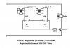
I don't know why my Periodic ON-OFF Timer don't work. They are two CD4541.
I don't know how Master Reset (MR) pin work.
LOW -> HIGH = stop oscillator, output unchange ?
HIGH -> LOW = start oscilator, reset counter, output change ?
I test by insert only the right chip. The output remain HIGH all the time.
I try to reset by apply V+ to MR pin, the output still HIGH.
I remove V+ from MR pin, the output still HIGH.
(The right chip set to Auto Reset when power on.)
Attachments
Last edited:
