Electro Tech is an online community (with over 170,000 members) who enjoy talking about and building electronic circuits, projects and gadgets. To participate you need to register. Registration is free. Click here to register now.
Welcome to our site! Electro Tech is an online community (with over 170,000 members) who enjoy talking about and building electronic circuits, projects and gadgets. To participate you need to register. Registration is free. Click here to register now.
Maybe if you could tell us what device you captured it from it might give a better clue. Better still, what chip was it at the input or output of?
Does not look like any special kind of protocol to me, just control signals for some kind of shift-and-load device, like 74HCT595 shift register chain, or graphic display maybe.
Trace 4 looks like a reset signal.
All just guesses with the minimum information provided.
This was captured from a smart card and card reader.
The way I interact with the machine is: I insert the card, the card reader displays the balance of credit on the card. I captured a sample of this interaction. I can post it tonight.
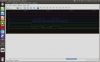
Next you press a button on the card reader. This reduces the balance on the card. The a above screenshot is of this communication.
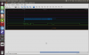
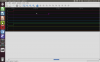
Trace 3 appears to be a clock... one that changes duty cycle and frequency, very strange. Traces 4 and 7 appear to be start and stop signals.
Trace 5 appears to be data. From the asymmetric high and low periods and the multiple clock pulses, it would appear to be some sort of NRZ format - like Differential Manchester encoding.
When the card is inserted into the reader, the reader displays the value. I reckon it is probably transferred to the reader through the contacts (The reader does not have a phone line).
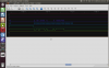
This is the communication when the balance is ten and balance zero. Strangely, they look pretty much identical (the first attachment is for 10 credit balance, the second is for no credit balance)
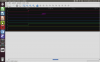
The only difference is in trace 2 at the very beginning of the signal (the third attachment is when there are no credits on the card. The last attachment is with 10 credit balance).
The first two certainly do look identical. Are you certain the card is being queried for the number of credits in this transmission? Simply reading the card may not be enough to do it, and if there are multiple transmissions the logic analyzer may only be grabbing the first.
Concerning those last two images: the violet trace on "no credits" looks more like an increasing PWM than data. For a chip that is powered by the reader, this may simply be an ordinary power-up glitch. Try reloading the "no credits" card with 10 credits and see how it compares.
This site uses cookies to help personalise content, tailor your experience and to keep you logged in if you register.
By continuing to use this site, you are consenting to our use of cookies.