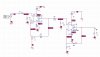
1) I changed the RC on the input of the LM741 to make it more like an audio amplifier.
2) The LM741 is not perfect. The data sheet: "input offset error voltage" is typically 1mV, worse case 5mV at room temp and could be as bad as 6mV. What that means is that the input is not perfect and there typically 1mV of error on the input pins. (could be as bad as 5mV) With your gain of 62 then the 1mV=62mV and 5mV=400mV of error at the output pin. (SPICE might not show this problem) Then you amplify again and the error is BIG. So I put a RC high pass filter between the amplifiers to remove the DC error.
3) The OPA501 also has in input error. Did not look it up but you will have the same problem here. So I added a 10uF cap to the bottom of R3. This causes the gain to decrease below 20hz. By DC the gain will be one. So the input offset error will be amplified by 1 not 93.
View attachment 118182
These fixes will help the offset.
--edited--
R6, C2 should be reversed.