Continue to Site

Welcome to our site!

Electro Tech is an online community (with over 170,000 members) who enjoy talking about and building electronic circuits, projects and gadgets. To participate you need to register. Registration is free. Click here to register now.

  • Welcome to our site! Electro Tech is an online community (with over 170,000 members) who enjoy talking about and building electronic circuits, projects and gadgets. To participate you need to register. Registration is free. Click here to register now.

I can't bootstrap a Buck converter!

Status
Not open for further replies.

Quank

New Member
Hi everybody,
- I am making a buck converter to go from 12 V to 4 V (more or less). The circuit is attached (Esquema 9_sinborde.png).
- Currently there are no control closed-loop. I'm regulating manually the frequency and duty cycle of the control signal (PWM) with a Function Generator. I use a 100 KHz signal with aprox 20% Duty Cycle.
- To control the NMOSFET I use the IR2186PBF driver with a bootstrap capacitor.
- At the moment the load is a resistance of 1 ohm (high power)
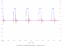
- Attached is a chart (Esquema18.png). In blue is the signal on the gate of the NMOSFET (coming from the driver). In red is the voltage Vs.
- As you can see, I can not increase the control voltage of the MOSFET above 12 V. This makes the MOSFET to no turning on properly, and as a result Vs becomes no very high.
- The supply voltage of the driver is 12 V. I am interested in powering the whole circuit at 12 V.

How I can get higher voltages to activate the MOSFET's gate abundantly (of the order of 20 V)?

The component values are the following:

Driver = IRS2186PBF
NXP MOSFET = PSMN1R8-30PL
D1 = STMicroelectronics STPS60L30CW
L1 = Abracon Corporation AIRD-03-8R2K 8.2 uH
Rgext = 200 Ohm potentiometer, regulated for the best results (few ohms)
Cbs = 47 uF 25 V
CBY = 2.2 uF 63 V
Dbs = FS 1N4934
VCC = Vin = 12 V
 

Attachments

  • Esquema9_sinborde.png
    Esquema9_sinborde.png
    67.9 KB · Views: 604
  • Esquema18.png
    Esquema18.png
    59.4 KB · Views: 377
If you want to achieve 20v this will have to be at least 2200uf @ 50v. You need to dump the coil breakdown voltage into the cap. Why is there two schottky diodes in parallel ? These should be after the coil.
 
Ok, I will try it.
I have two schottky diodes in parallel because it is incapsulated in the same package TO-247 (STMicroelectronics STPS60L30CW). Must I use only one leg of the diode package and let the other one not connected?
What you mean in saying "These shoud be after the coil"? You mean that the Cout is after the coil, of course?
 
How I can get higher voltages to activate the MOSFET's gate abundantly (of the order of 20 V)?
Won't a gate voltage > drain voltage damage the FET?
The FET you are using is specified as logic-level. Does it really need > 12V on the gate to turn it fully on?
I think the reason you are getting a low output voltage is because you have a very low value load resistor. In simulation I get only 0.85V out with a 1 Ohm load (~4V out with a 10 Ohm load).
 
Alec_t:

1.1 General description of the MOSFET:
Logic level N-channel MOSFET in TO-220 package qualified to 175 °C. This product is
designed and qualified for use in a wide range of industrial, communications and domestic
equipment.
1.2 Features and benefits
High efficiency due to low switching
and conduction losses
Suitable for logic level gate drive
sources
1.3 Applications
DC-to-DC converters
Load switching
Motor control
Server power supplies

As you can see is not only specified as for logic-level. I think is a goog Buck converter FET.
I need a buck converter for having a Vout INDEPENDENT of the load. So if I put a 10 Ohm in the load I want to have the same as if I put 1 Ohm (diferent current of course)!!
I don't need 12 V for turning the FET. I only need more or less 14 V because the source is changing its tension from 0 V to 12 V. But if I want to have little Rdson I have to operate with high Vgs.
I think you are wrong with it.

Thank you
 
Hi.

Shouldn't a P-channel fet be used and swap source/drain?

Just mentioned since "standard" mosfet circuit is the quite opposite.
 
The P-MOSFET is discarded because of price and eficiency. I'm sorry but I've studied this choice for enough time. There are some pros and cons, but now I don't want to change...
Thanks for your answer.

Quank
 
is not only specified as for logic-level. I think is a goog Buck converter FET.
I'm sure it can be used in a 12V-supplied buck converter. But I think you have misunderstood what a 'logic-level FET' is. It means that with a logic-level (i.e. 5V) gate-source voltage the FET is guaranteed to switch on.
 
To raise the gate voltage you could apply the drive pulses via a capacitor (C1 in the attached).
 

Attachments

  • Buck.gif
    Buck.gif
    16.1 KB · Views: 1,162
To raise the gate voltage you could apply the drive pulses via a capacitor (C1 in the attached).
buck-gif.57680
You're missing the diode in the buck converter part and AC-coupling the drive signal to the gate will not give the required swing to both turn the mosfet fully on or off.

The original schematic drawn by Quank looks like the one in the datasheet, and should be suitable; that is if the component values are appropriate. The gate voltage is ~12V higher that the source voltage, so the chip is not doing anything wrong in that regard. It is acting as though the mosfet source is connected to ground though. Is the inductor of a suitable value? Can you post the part values?
 
You're missing the diode in the buck converter part and AC-coupling the drive signal to the gate will not give the required swing to both turn the mosfet fully on or off.
I simulated the above circuit both with and without the diode you refer to and found (surprisingly) it made no significant difference. Simulation shows the FET switches both fully on and fully off. D1 prevents the gate going negative of the source and bootstraps the gate voltage (for the components shown the gate voltage rises to ~16V). R3 is the typical oscillation-damping resistor, but in addition I assumed for simulation purposes that the gate drive voltage-source had an impedance of 150 Ohm.
Is the inductor of a suitable value? Can you post the part values?
Simulation shows L to be too high. The OP has already posted part values in post #1.
 
Last edited:
I simulated the above circuit both with and without the diode you refer to and found (surprisingly) it made no significant difference.
That should be ringing some alarm bells then; it's because the mosfet is always on and the inductor current just passes through the mosfet the whole time.

Simulation shows the FET switches both fully on and fully off.
No it doesn't. What's the voltage on the FET gate? If it's not above 12V, the FET is is not fully on.

for the components shown the gate voltage rises to ~16V
Really? I don't believe that.

The OP has already posted part values in post #1.
Thanks, I missed that.
 
@ dougy
Perhaps this will convince you :). I've included the asc file if you want to run the sim.
 

Attachments

  • Buck.asc
    1.9 KB · Views: 170
  • BuckScreenPrint.gif
    BuckScreenPrint.gif
    29.4 KB · Views: 287
alec_t,
From the first post, it looks like you are working on a buck PWM.
If you are just looking at gate drive then ...OK.
If you want a buck converter then this is not a good one. I have not run it on spice but, it looks like while the current builds up in the inductor, there is current in the MOSFET, that part is good. While the current in the inductor ramps down there is current flow in the MOSFET that is NOT GOOD!. You are missing a power diode form the MOSFET-drain to gnd.
 
@ dougy
Perhaps this will convince you :). I've included the asc file if you want to run the sim.
Ok, you're quite right re the gate voltage reaching 16V; I've been converted, I'm a believer!

It doesn't change the fact that the circuit doesn't turn the mosfet fully off while the inductor current is flowing. It's not a good converter.
 
Quank, Your circuit should work: however the bootstrap capacitor is much to large at 47Ufd. Usually 10X the FET gate capacitance is a good rule of thumb. You might want to check the bootstrap diode to make sure it didn't pop the first time 12 volts was applied. I didn't see trace names on the scope picture, but gate and source would be nice.
 
Status
Not open for further replies.

New Articles From Microcontroller Tips

Back
Top