Electro Tech is an online community (with over 170,000 members) who enjoy talking about and building electronic circuits, projects and gadgets. To participate you need to register. Registration is free. Click here to register now.
Welcome to our site! Electro Tech is an online community (with over 170,000 members) who enjoy talking about and building electronic circuits, projects and gadgets. To participate you need to register. Registration is free. Click here to register now.
Your circuit has a output which goes form +5 to almost -5V because of V2, V3.
The input turns on when V1 is larger than -4.7V (or 0.7V above V3). The only time the circuit is off is when the input is below -4.7V.
A transistor responds to current in the Base. Current flows into the Base when B-E voltage is above 0.7V.
can you explain a bit more what's happening inside the circuit? I know it works as a switch. What's the different with the circuit above and the one below? I really understood the simplest circuit below. But I just don't know how to analyse the circuit above like why must it be at -4.7V and the graph looks so different from this one.
Many people, new to transistors, read that if you apply 0.7V to a Base or 10V to a Gate of a MOSFET the part turns on. That is not true. You need to apply this voltage from Base to Emitter (Gate to Source).
In this circuit the transistor can not know where ground is. The emitter is at -5V so the turn on voltage is -4.3V. (Base-Emitter=0.7V)
To be more accurate the transistor Base responds to current not voltage.
In my opinion, if I wanted to build an amplifier circuit, I'd consider a higher current gain BJT so that my signal can be amplified at its best. This gives me with T2 and T3. I'm not so sure with the rest parameters, thus it leaves me here wihtout a definite answer.
for switch circuit, I'd consider the least power losses. The fact that using BJT will give us power loss due to switching from cut off and saturation region, this thing is something that we can't surely avoid. But of course, a best switch is when there's no power losses on it. Thus, I will choose T1? I hope you could help me
A good amplifier has a high voltage gain so that plenty of negative feedback can be used to reduce distortion.
Current gain (beta) is not voltage gain.
A transistor has a maximum allowed voltage, current and amount of heating.
A transistor used as an amplifier has some distortion that is reduced by adding negative feedback that also reduces the voltage gain.
A transistor used as an amplifier needs to have its input biased with R3, R4 and C1 in my circuit so that its input and output can swing smoothly up and down.
The hFE (beta) of the transistor determines its input bias current from 3 and R4.
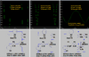
I simulated with a 2N3904 transistor;
1) No input bias, 1.25V peak sinewave input and 2.5V output. The output is severely clipping into a rectangular wave.
2) No input bias, 0.73V peak input (so that the transistor barely turns on) and about 2.2V peak output. Again, severe distortion.
3) Simple input bias, 0.03V peak input producing 1.3V peak output. High voltage gain of 144.3 times but fairly high distortion.
This site uses cookies to help personalise content, tailor your experience and to keep you logged in if you register.
By continuing to use this site, you are consenting to our use of cookies.

")