Continue to Site

Welcome to our site!

Electro Tech is an online community (with over 170,000 members) who enjoy talking about and building electronic circuits, projects and gadgets. To participate you need to register. Registration is free. Click here to register now.

  • Welcome to our site! Electro Tech is an online community (with over 170,000 members) who enjoy talking about and building electronic circuits, projects and gadgets. To participate you need to register. Registration is free. Click here to register now.

Humidity sensor circuit

Status
Not open for further replies.

Asjad

New Member
Dear Folks,

I am trying to interface a PIC to a

Philips -> humidity sensor (capacitive varying).

From the datasheet it says

10% RH = 112pF
90% RH = 142pF

What kind of circuit could detect such samll changes???

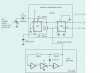
The datasheet suggests this circuit BELOW


WHERE IS THE OUTPUT TO THE PIC??

Any easier circuits???


Thanx!
 

Attachments

  • hee.jpg
    hee.jpg
    43 KB · Views: 723
Asjad,

There are two outputs on this circuit! The top half uses two D-type flip flops. The second one (FF2) is the one that contains the outputs. On the right of it are two connectors, Q and NOT Q, (Q with a bar above it). The one that you need to connect to your PIC is the Q output.
All the NOT Q output does, is give you an inverse of the Q output. So, say there was +5v on Q, there would be -5v on NOT Q.

As for the bottom half of the circuit. That is just an oscillator circuit. Which provides FF2 with a clock pulse.

I would use this circuit, if it was on the datasheet then it will have all the right characteristics and ratings for your PIC in that particular circuit. So good luck!
 
Status
Not open for further replies.

Latest threads

Back
Top