Continue to Site

Welcome to our site!

Electro Tech is an online community (with over 170,000 members) who enjoy talking about and building electronic circuits, projects and gadgets. To participate you need to register. Registration is free. Click here to register now.

  • Welcome to our site! Electro Tech is an online community (with over 170,000 members) who enjoy talking about and building electronic circuits, projects and gadgets. To participate you need to register. Registration is free. Click here to register now.

HT12E beeper system

Status
Not open for further replies.

zachtheterrible

Active Member
I have made everything else for a little beeper system for my friends shop so that when someone walks through the door you will know. Its wireless by the way.

Im having some trouble with the receiver end of the system unfortunately.

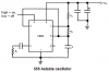
In my schematic, the farthest left is an RF module, followed by the HT12E, then two 555's, the first creates a delay for the other 555 to stay on, and the next 555 makes the buzzer go 'beep beep beep'.

For some odd reason, the setup is not working at all, and I can see the square waves of the second 555 at the output of the RF module. It will also start beeping on its own, with beeps that decrease in frequency from about 10 HZ to 3 HZ.

Is my schematic correct?
 

Attachments

  • beeper.jpg
    beeper.jpg
    91.8 KB · Views: 428
Hi Zach,
The ordinary 555 is powerful and fairly fast and therefore draws a few hundred mA from the supply when its output switches. It needs a lot of supply filtering to keep the supply spikes out of other circuits. The current spikes are probably upsetting your receiver.
Cmos 555's like LMC555 or TLC555 have a much lower supply current spike, but also less output power.

You do not have a current-limiting resistor from the 1st 555's output to the base of the transistor. The 200mA from the 555 could destroy the 555 and transistor or quickly kill a battery.

You seem to be turning on the 2nd 555 oscillator by using the transistor to ground its pin 1. Usually the reset pin 4 is used to gate it.

You have the beeper DC-coupled to the output of the 555, if it is a piezo then the DC might reduce its life and output, and if it is a speaker then the DC will offset its cone reducing its output. Use an output coupling cap.

Your 2nd 555 oscillator looks odd. This one is standard:
 

Attachments

  • 555_oscillator.png
    555_oscillator.png
    12.1 KB · Views: 359
Hey audio, my second 555 works just fine with a fewer part count so ill keep that :lol:

As for the piezo, its a self driven, so it requires DC.

Ill try those things though and see if i cant get it to work.
 
Hi Zach,
Wire the 555's like this:
 

Attachments

  • beeper_100.jpg
    beeper_100.jpg
    42.1 KB · Views: 350
Status
Not open for further replies.

Latest threads

New Articles From Microcontroller Tips

Back
Top