Continue to Site

Welcome to our site!

Electro Tech is an online community (with over 170,000 members) who enjoy talking about and building electronic circuits, projects and gadgets. To participate you need to register. Registration is free. Click here to register now.

  • Welcome to our site! Electro Tech is an online community (with over 170,000 members) who enjoy talking about and building electronic circuits, projects and gadgets. To participate you need to register. Registration is free. Click here to register now.

How Would I Do This?

Status
Not open for further replies.

LiquidOrb24

New Member
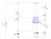
Lets say I have a series of pulses from a 555 timer going at about 1 Hz. I want one pulse to turn on lets say a Blue LED, and the second pulse on the 2nd second turn on a different LED of maybe the same color, and the 3rd pulse to turn back on the 1st Blue LED and so on...Basically altering LED's that turn on.

Would a Demultiplexer work? or would some sort of other logic IC work.

For some reason I think it's some sort of simple solution but I dont see it...I think I'm thinking too much :(
 
Attach is a simple 555 circuit to flash 2 LEDs alternately...
 

Attachments

  • AltFlash.jpg
    AltFlash.jpg
    43.8 KB · Views: 154
That would work perfectly HarveyH42 except I was hoping to somehow drive the two LED's from a single pulse from a PWM of a microprocessor from 1 output pin. I was going to ease that into the first post earlier but for some reason didnt.

I basically want 1 pulse from the pwm to turn one LED on and the next pulse to turn the other one on and so forth without a 555 timer, Perhaps even with a manual pushbutton switch as a demo before the microprocessor.

Ron H...Those forums did help some...none really dealing with my particular problem but I did see a J-K flip-flop or D-Latch flip-flop that I might be able to work with but still am not sure how those can store the latest state of the LED and switch to the next LED output.

Thanks all for replying and keep doing so if any ideas spring up.
 
A Chaser circuit uses a CD4017 counter/decoder. Its 10 outputs step one after the other. It can be stepped with an oscillator or a debounced pushbutton. Its sequence of 10 can be shortened by connecting the next output not wanted to its reset pin.
 
Use JK flip flop 74114. Both J & K set to 1. CLR and PRE set to 1. Give the pulses to the CLK input. 74114 is a negative edge triggered. You can check if this suits your application. If not you can search a JK FF with positive edge trigger.

Aily
 
The 74114 TTL flip-flop is old, needs a 5V regulated supply and is very power-hungry. Use a Cmos logic IC instead.
 
I was hoping to somehow drive the two LED's from a single pulse from a PWM of a microprocessor from 1 output pin.
You'll probably need to change the resistor values for proper LED bightness, but you can basically do the same thing as HarveyH42's 555 example but like this:
 

Attachments

  • MIcroLEDs.gif
    MIcroLEDs.gif
    3.8 KB · Views: 136
The output of a PIC has a max current rating of 25mA. The two LEDs in series at the output could have the resistors calculated for less than 25mA and the LEDs will alternately light, but one each one might only dim instead of turning off. Reduce the current by increasing the value of the resistors to make it work properly.
 
Status
Not open for further replies.

New Articles From Microcontroller Tips

Back
Top