Continue to Site

Welcome to our site!

Electro Tech is an online community (with over 170,000 members) who enjoy talking about and building electronic circuits, projects and gadgets. To participate you need to register. Registration is free. Click here to register now.

  • Welcome to our site! Electro Tech is an online community (with over 170,000 members) who enjoy talking about and building electronic circuits, projects and gadgets. To participate you need to register. Registration is free. Click here to register now.

How would i build this circuit?

Status
Not open for further replies.

RJamerson

New Member
Hi guys, i'm working on a project that requires two LED's and three switches. Let me start by saying i know almost nothing about electronics, but another forum recommend I ask you guys for help!

------------------

Okay, so this is the scenario:

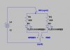
One LED is green and the other is red. There is one switch to choose the red LED and one switch to choose the green LED, the third switch is the 'power switch' which will cause whichever LED you have chosen to light up.

After the power button has been pressed the circuit doesn't reset, so if i pressed the RED BUTTON, then POWER, the RED LED would light up, i'd then be able to come back to the circuit two days later and press the POWER button and it would still light up RED. (sorry for all the caps, just trying to make myself clearer)

Oh, and it's important that pressing the GREEN BUTTON, then pressing the RED BUTTON turns OFF the GREEN LED and turns the RED LED ON -- so they cut each other off.

--------------------

Sorry if this isn't clear enough, please feel free to ask any questions!

Many thanks in advance! :)
 
Hi,

Do you have to use push buttons? If so, you can look into "push on, push off" types. They hold their state indefinitely.
 
Hi,

Do you have to use push buttons? If so, you can look into "push on, push off" types. They hold their state indefinitely.

Hi, the only problem is that i need them to cut off each other, so if i press red, then power, the red light comes on, but then if i press green with out turning red off, then power only green comes on.
 
A D type flip/flop (latch) with Set/Reset inputs would work (74HC74) . The RED button sets the f/f, the GRN button resets it. (note: the switch ties the corresponding input to ground to set/reset).
From here you can go two ways:
1. connect the Q output to the anode of the RED LED and the /Q output (Q not) to the anode of the GRN LED. Then, the power switch would tie to both LED cathodes, to ground.
2. connect the Q output to the cathode of the GRN LED, and the /Q output to the cathode of the RED LED. The power switch would then tie to both anodes, to +LED

(note, there should be a resistor between +, LED+, LED-, and GND, somewhere in the loop.)
 
Does this do what you want? Any time you flip the ON switch, the LED selected by the GREEN/RED switch lights up. The spdt switch "remembers" which position it was in last.


This is a project where wanting to use momentary switches does nothing but complicate your life.
 

Attachments

  • LedSw.jpg
    LedSw.jpg
    52 KB · Views: 174
You could almost do it directly with a dual coil magnetic lathing relay such as this one: **broken link removed**

You do need a power source capable of 5 V and about 30 mA + the current for the LEDs. a 5V wall wart would work fine. The gizmo would not consume any power when off and the power could be disconnected.

I get the feeling that the states are red or green and both OFF and both off are invalid.

If that's the case, the DPDT relay can supply current limited power (say 20 mA) to the LED. So, one resistor and two LEDs.

Using a dual coil latching relay, you just need to supply the correct polarity PULSE to one of the coils. So, you need to apply +5 to one coil using one switch and +5 to the other using a switch, observing polarity.

Except for the power supply the parts count is:
RED LED
Green LED
Current limiting resistor RL
DPDT dual coil latching relay
Two SPST push buttons
One SPST power switch
DC Barrel jack of the right size: 5.5/2.1 and 5.5/2/5 are popular

And the usual case and LED mounting hardware etc.

5 V 1 A wall wart.

If you want battery power, we can work on it. You just need about 30 mA to run the LED and a 30 mA pulse.
 
Last edited:
Hi, the only problem is that i need them to cut off each other, so if i press red, then power, the red light comes on, but then if i press green with out turning red off, then power only green comes on.

Hi,

Ok, i think you can do that too if you can find any 4PDT push button switches, and you limit it to just RED and GREEN (only two colors of LEDs) that you want to work that way.
This would be nice as it would be purely a matter of wiring up the two switches properly, but it does depend on you finding two 4PDT push on/push off type switches that you like enough to use for the project.
That would be all that is required however (no IC chips required) except of course for the current limiting resistor for the LED's.

If you cant find those push button switches, you can definitely find the toggle type switches that are 4PDT if you didnt mind using toggle switches instead.

If you are interested in this approach i'll draw up a schematic.
 
Status
Not open for further replies.

Latest threads

New Articles From Microcontroller Tips

Back
Top