Continue to Site

Welcome to our site!

Electro Tech is an online community (with over 170,000 members) who enjoy talking about and building electronic circuits, projects and gadgets. To participate you need to register. Registration is free. Click here to register now.

  • Welcome to our site! Electro Tech is an online community (with over 170,000 members) who enjoy talking about and building electronic circuits, projects and gadgets. To participate you need to register. Registration is free. Click here to register now.

How to turn ON mosfet?

Status
Not open for further replies.

ctag06

New Member
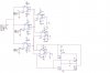
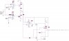
In my final year project, i have to simulate full bridge inverter using PSpice. In this project, two comparators uA741 were used to give supply for the N-channel Mosfet. But the problem is, when i try to simulate my work mosfet can't turn ON because the value of Vgs for the mosfet is less than 12V. Can somebody help me what should i do to make sure this mosfet can operate properly.
 
I don't understand your setup. Please post a schematic.
 
or at least the MOSFET number you are using.
 
Last edited:
Turn on a MOSFET: low lighting, soft music and champaign...

Seriously, post a schematic.
 
Last edited:
Agreed with all foregoing posts.

Post your schematic and you'll certainly find a solution. (or the great community of members will direct you to the right way).

Flowers to everyone concerned with that problem! :)

We're the greatest! :eek:
 
Hai,

Thanks for reply. I admit that i'm too late to know about this...but i really really hope someone can help me to solve this problem.
 
Please post a .jpg or otherwise readable version of your schematic, and not a zipped version, and I'll take a look at it.
 
Please post a .jpg or otherwise readable version of your schematic, and not a zipped version, and I'll take a look at it.
Please do not save your schematic and post it as a fuzzy JPG file type. Please save it and post it as a very clear PNG file type instead.
 
Hai BrownOut and audioguru,

Sorry guys for my mistake...I hope this attachment could work. Anyway, thanks a lot for reply me.
 

Attachments

  • Schematic_1.JPG
    Schematic_1.JPG
    66.1 KB · Views: 280
The inputs on the 741 opamps are not biased so they will not work. Their output high voltage is +3.5V but your lower Mosfets need a gate voltage of +10V and the upper Mosfets need a gate voltage of +180V to turn on.
 
Is there some reason you're using +/-5V for your op-amps? Is there any reason you're using all N-FET's for your bridge circuit? If your high side FET's were P-FET's then the bridge might work, but you would need to deive the gates to very near the 170V to trun them off. You would need an extra transistor on each input side to translate the voltage.
 
Last edited:
Hello audioguru,

sorry for being late. So, what should i do with my op-amp to make sure they will work?
 
Hai Brownout....

i dont have any idea why i put -/+5V for my op-amp because i really new with this part and i just lookin the source from internet and try that value...so bad right? and actually i want to use all N-channel mosfet because i'm already buy the n-channel for my project and IR2181 as it driver. I want to try your suggestion but I don't really understand about an extra transistor on each input side. using the same transistor? Can you post to me your drawing? Sorry and thanks a lot for reply me
 
The lousy old 741 opamps are much too slow. While they are slowly ramping the gates of the Mosfets then the Mosfets will be quickly heating and might burn out.
Use real comparators if you want which switch much faster.
 
thanks a lot for your advice. I'm really sure it will help me for my simulation stage...I'll try to use real comparators as you said. Thanks again and i really appreciate it...
 
Hi Brownout....

I've tried to do the simulation like your advice....This is what do you mean?you can see the attachment. please correct me if i do wrong.

Thanks.
 

Attachments

  • try..JPG
    try..JPG
    70.4 KB · Views: 212
Status
Not open for further replies.

Latest threads

Back
Top