Electro Tech is an online community (with over 170,000 members) who enjoy talking about and building electronic circuits, projects and gadgets. To participate you need to register. Registration is free. Click here to register now.
Welcome to our site! Electro Tech is an online community (with over 170,000 members) who enjoy talking about and building electronic circuits, projects and gadgets. To participate you need to register. Registration is free. Click here to register now.
OK. I thought maybe there was a reason it would not work for you. The circuit would be better if the resistor was a 100K pot and the capacitor 1/10 the size. It needs to be a Schmitt trigger inverter like the one shown.
OK. I thought maybe there was a reason it would not work for you. The circuit would be better if the resistor was a 100K pot and the capacitor 1/10 the size. It needs to be a Schmitt trigger inverter like the one shown.
Looking at your circuit, I noticed that I am already using a schmitt trigger MM74HC14M in the same circuit to invert the PLL output before feeding into LM556. I am not using all the circuits in it anyways, so I guess I can use one of those. I hope it wont be a problem for other circuits in that IC. Once I get this working, I am gonna move on to the LM556 part.
Tried this and its working fine. The only think that I changed is to use 15V rather than 12V as I can see some distortion in the rising edge of the output at 12V. This can be used into my design, but I have access only to 5V on my digital board, are there any other variations of this using 5V or should it have to be above 12V?
Thanks Eric. I will try this one too.. I am just trying to decide which one to go for, analog or digital..... I will check which one is more reliable. One thing that I see in using analog is the sine amplitude reduces going through your circuit which is somewhat a problem for us as our sine amplitude starts from 0 and we would like to lock on it as soon as the amplitude of it changes. I hope it wont be a big problem for us, will see..
OK. I thought maybe there was a reason it would not work for you. The circuit would be better if the resistor was a 100K pot and the capacitor 1/10 the size. It needs to be a Schmitt trigger inverter like the one shown.
I got it working with a 220p cap and 150K pot and Vcc decoupling. Its still jittery if I go more offset.
Both designs are working, thanks. I will use digital for now after the PLL and try to use analog design once I get the PLL working with sine wave so that I can use this offset design before the PLL.
Later on in the circuit I am using 556 dual timer to delay the square wave and also to change the duty cycle of it. As I said earlier, I was not able to adjust much at all with LM556CMX IC nor LM556CN (in which case I don't see any output at all). Then to my luck, I found ALD7556 IC and thought I would give it a try. This worked great. Same circuit on the breadboard, just changing the IC. Do you guys have any ideas why it would be like that?
Thanks for that info. LM556 is working with TTL trigger, but narrow adjustment range while ALD7556 has more range and stability too even with a TTL trigger. The input for my LM556 is the output from a 74HC14 hex inverter whose input is the output of a 4046 PLL. I guess I can safely use ALD7556 inplace of my LM556.
I noticed something new in my PLL circuit that the output has jitter. The exact same circuit works without phase jitter on another PCB with the same PLL design. Any suggestions?
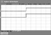
The input itself is very stable at 15.2Khz as you can see in the picture on channel 4.
This site uses cookies to help personalise content, tailor your experience and to keep you logged in if you register.
By continuing to use this site, you are consenting to our use of cookies.