Kavitha Seetharaman
New Member
Hii ..
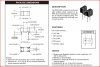
I'm using the optocoupler MOC7811 for my project . But i dont know how to check it whether it's working or not ... Can anyone help me getting its circuit .... Also, please tell me thw working of this optocoupler ....
Thank u
- Kavitha
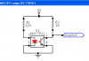
I'm using the optocoupler MOC7811 for my project . But i dont know how to check it whether it's working or not ... Can anyone help me getting its circuit .... Also, please tell me thw working of this optocoupler ....
Thank u
- Kavitha