Continue to Site

Welcome to our site!

Electro Tech is an online community (with over 170,000 members) who enjoy talking about and building electronic circuits, projects and gadgets. To participate you need to register. Registration is free. Click here to register now.

  • Welcome to our site! Electro Tech is an online community (with over 170,000 members) who enjoy talking about and building electronic circuits, projects and gadgets. To participate you need to register. Registration is free. Click here to register now.

How to reduce current?

Status
Not open for further replies.

Lac

New Member
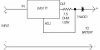
I'm currently building a battery-charger based on **broken link removed** ciruit, but I can't seem to figure out how to reduce current flowing, without getting a massive voltage drop.

I tried with a resistor in serie, but the voltage dropped below the voltage of the battery to be charged, making the circuit useless. The reason for that I want to reduce the voltage is that the batteries are going to stand in trikle-charge-mode constanly. Being a part of a backup circui, in case of power failure.

The battery to be charged is a 180mAh 7.2V, I can't remeber if it was NiCad or NiHm. Supply voltage is +14.8VDC.

**broken link removed**

Cheers!
Lac.
 
You could probably experiment and eventually find a resistor that works however as the current changes (battery changes as it charges) the resulting voltage will change.

Battery charging can get pretty elaborate however to keep it simple I'd use a 3 terminal voltage regulator configured as a current regulator. Look up the datasheet for an LM317 and you should see the current regulator arrangement and the formula (real simple) for selecting the resistor ( you only need one). I don't know what to tell you about how much current. I've heard 20 or 30 ma as a limit. From my point of view it would be to apply as much current as the supply will allow without overheating or damaging the batteries otherwise.

The better charging schemes look at voltage, current, battery temperature and changes in charging current. The better charging schemes address things like safety (overheating battery), optimum battery life, charging time, float/trickle charge, etc.
 
Thanks! But where in the circuit should I put the resistor? I just can't get it right without getting that darn voltage drop :?

Cheers!
Lac.
 
In your application I would configure a 3 terminal regulator such as the LM317T or LM317LZ as a constant current regulator for the charge current of about 16Ma. In doing so the battery will never overcharge and you can leave the charger connected all the time. I would connect a 75 ohm resistor between the adj, and out terminals of the the regulator. Break the connection where the anode of the 1N4001 and the LED connect.
connect the input of the regulator to anode of the LED and in + from the
wall wart. Connect the adjust terminal of the regulator to the anode of the 1N4001. The 1N4001 will protect the circuit if you happen to connect the battery up backwards. The regulator will only supply about 16Ma of current to charge the battery and the battery will seek its on level, approximately 9V. This way the battery will never over charge.
I have been building chargers for both Ni-Cad and Ni-Mh for years this way. The recommendation is to charge at rated capacity X.095. In your case it is 180 X .095 = 17.1 Ma. However the closest standard resistor is
75 ohms, which reduces the current to about 16Ma. 1.2/75 ohms = 16Ma.
 
Looks nice. Do you have any schematiccs of this? How do I wire a voltage regulator so that it acts as a current regulator?

break connection betwenn the diod and the led. place the input of the regulator to the + from the wall, output to the LED and ADJ to the diod. Am I right?

Cheers!
Lac.
 
Lac- when current flows thru a resistor there is a voltage drop - that's what the resistor is supposed to do. How much voltage drop is dependent on how much current is flowing. How much current flows depends on the condition of the batteries and the characteristics of the power supply. The resistor would be in series with the batteries.

If the supply voltage is 14 volts and the nominal battery voltage is 7.2 volts just about any resistor will allow current to flow. If you measure the battery before starting to charge then apply the charger with series resistor you might not see a significant increase but the battery voltage should not drop - unless you've got the polarity wrong or a diode has failed. What should happen is the battery voltage should rise as it charges and the current should drop - resulting in less voltage drop across the resistor.

Some simplification might allow you to select a resistor value as a place to start. If the batteries look like a dead short circuit (worst case) and you wanted to limit the current to 50 milliamps you would put a 280 ohm resistor in series with the batteries. With a 14 volt drop across the resistor and 50 milliamps flowing you'll need to dissapate 0.7 watts of power - so use a 1 watt resistor. As the battery voltage rises toward 7.2 volts the current ought to drop to between 20 and 25 milliamps. If you can't get 1 watt resistors you can parallel resistors to get the net resistance and power dissapation. The problem - with something between 20 and 50 milliamps of current flowing - will that overheat the battery?

Note that all of this assumes that your power supply can deliver whatever is needed.
 
Lac said:
Thanks! But where in the circuit should I put the resistor? I just can't get it right without getting that darn voltage drop :?

Fit the resistor in the positive lead to the battery (it could go in loads of different places, but that's the most common).

As already suggested the voltage is supposed to drop, that's what the resistor is there for, it will drop to the voltage it's supposed to be - the charger itself should provide more voltage than required. The voltage on the top of the battery will gradually increase as the battery charges, and the charging current will decrease accordingly, it's all governed by ohms law.
 
Ok, I meant a 1800mAh battery not 180mAh.

But basically I cant simply "only" use a resistor to charge a battery.

If you have a supply of 14,8V, and limits the current to 171mA (desired current used to charge battery) with only a resistor (86ohm 2.5W) in serie, the voltage drop will be far to big, and will not supply the battery with enough voltage to charge it fully (7.2 needed, at least)

If you use a lower rated resitor to get a lower voltage drop, there will be enough voltage across the battery, but the current supplied to the battery will be far too much, and eventually make the battery overheat.

So, what you need is another way to limit the current to the battery, without getting a significant voltage drop.

The solution: A voltage regulator configured as a current regulator. A LM317 with a 7.3ohm (something close to that, wich is buyable) resistor between the OUTPUT and the ADJ pins. That would supply 171mA to the battery without any voltage drop.

puh! Have I got it right? :wink:

Cheers!
Lac.
 
Lac said:
Ok, I meant a 1800mAh battery not 180mAh.

But basically I cant simply "only" use a resistor to charge a battery.

If you have a supply of 14,8V, and limits the current to 171mA (desired current used to charge battery) with only a resistor (86ohm 2.5W) in serie, the voltage drop will be far to big, and will not supply the battery with enough voltage to charge it fully (7.2 needed, at least)

Yes you can, because that doesn't happen (there's no way it can), a simple resistor like that works just fine - and is how most commercial chargers work.

As long as the source voltage is higher than the target battery, current will flow - and the higher the source voltage (and the larger the resistance) the more constant the current is.

It all calculates very easily with ohms law:

V is the voltage across the resistor, and is the source voltage minus the battery voltage - so using the figures above, V = 14.8-7.2 = 7.6V. The resistance is 86 ohms (from above), this gives current = V/R = 7.6/86 = 88mA.

Your 171mA above used the entire source voltage in the calculation, which is incorrect.
 
The LM317 (or similar regulator) is a simple way to do what you want to do and it is the approach that I would take in a similar situation. It might not provide the fastest charge rate or result in maximum battery life but it will probably be good enough.

The resistor with a 14 v DC supply will work but is a poorer choice than the LM317. Lots of low cost commercial battery chargers are no more than this. They work, the people that use them are satisfied and for many situations they wouldn't notice the difference between that an a more complex charger.
 
hmm.. in wich applications are LM317s used? PC powersupplies? I'm short on money right now, taking compnents from old, broken devices are always cheaper. :wink:

Cheers!
Lac.
 
Here is the schematic. In the US the closest standard value of resistor is
7.5 ohms. Although the calculated value comes out to 7.02 ohms.
 

Attachments

  • charger_126.jpg
    charger_126.jpg
    13.1 KB · Views: 522
Bear in mind that the LM317 solution will drop about 4V in my experience. You'll be O.K. at 14.8V, but you could be pushing it at 12V. Some LM317s are low dropout, these are better for constant current charging cicuits, IMHO.
 
thanks for the notice. how are these low dropout regulators marked? wich letters?

Cheers!
Lac.
 
Status
Not open for further replies.

Latest threads

New Articles From Microcontroller Tips

Back
Top