Continue to Site

Welcome to our site!

Electro Tech is an online community (with over 170,000 members) who enjoy talking about and building electronic circuits, projects and gadgets. To participate you need to register. Registration is free. Click here to register now.

  • Welcome to our site! Electro Tech is an online community (with over 170,000 members) who enjoy talking about and building electronic circuits, projects and gadgets. To participate you need to register. Registration is free. Click here to register now.

How to read a datasheet (74LS04)

Status
Not open for further replies.
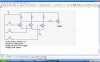
When 15VAC is rectified and filtered with a capacitor then it gives 20VDC. If the transformer is little and isn't loaded to its max current rating then the DC could be as high as 30V. A 7805 regulator will smoke with such a high input voltage and the high output current of old TTL logic ICs.
 
Smoke?

audioguru said:
A 7805 regulator will smoke with such a high input voltage and the high output current of old TTL logic ICs.

Hmmmmm...I kinda have to disagree with that. The 7805 is rated for 35 volts and the amount of current a single 7404 (much less a 74LS04) will hardly tax a regulator that is often used to supply boards with 20 or 30 TTL ICs with ease.
 
crashsite said:
Hmmmmm...I kinda have to disagree with that. The 7805 is rated for 35 volts and the amount of current a single 7404 (much less a 74LS04) will hardly tax a regulator that is often used to supply boards with 20 or 30 TTL ICs with ease.
You are kinda correct.
The absolute max input for a Texas Instruments uA7805 is 35V but they recommend a max of 25V.
A logic board with 20 to 30 TTL ICs will have an input to its 7805 of 8V, not 30V.
The 7805 has a typical operating current of 5mA and the 74LS04 without a load uses 5mA so the power dissipation in a 7805 is low. It won't even get warm.

This is the first thread 2 pages long that doen't have a schematic.
 
Maybe this can help
Use proper power rating components. And keep in mind that no failsafe is in this design. no need to convert the 15V again to 5.

Please verify with more experienced designers
see attached file
 

Attachments

  • image002.jpg
    image002.jpg
    40.1 KB · Views: 182
I'm Confused

shirazmacuff said:
Use proper power rating components. And keep in mind that no failsafe is in this design. no need to convert the 15V again to 5.

I'm not just sure what that circuit is supposed to do...or how.
 
the base of the 3 transistors in line will take the input from your sensors in the tank and then send a signal to the driver transistor to the right. keep in mind that the transistor on the right is pnp and all the others are npn. any one of the 3 transistors when foward biased by your transducer in the tank will send a negative bais to the pnp( far right) . and inturn output approx 14.4 volts on the collector( this is depending on the load).
so you have 3 inputs which will turn the driver on even if one input is high or 2 input is high or 3 input is high. this means that the you have to setup the swithes in the tank to turn on when the water is low. i hope this helped
 
See image for explanation
What type of pump are you using?
Remember that water and electricity are lethal combination
 

Attachments

  • image002.jpg
    image002.jpg
    193.8 KB · Views: 160
The schematic has 3 collector resistors in parallel. Only 1 is needed.

The input transistors will blow up when a switch is turned on becase the bases don't have series current-limiting resistors.

I tried to remove the millions of dots but couldn't because the schematic is a very fuzzy JPG file type.
Schematics should be saved and posted as a very clear GIF or PNG file type.
 
shirazmacuff said:
See image for explanation

Well, I wasn't one of the originators of the practical application but, I see a couple of things. You've essentially invented the 3-input NOR function in your logic.

Water and electricity aren't really lethal at these voltages but, you could get some nasty corrosion over a few weeks.

There is a problem with your circuit. If you close any of the switches you'll short the BE junction (a forward biased diode), of the associated transistor, between your supply voltage and ground with no current limiting device. That'll smoke the poor transistor.
 
How about this one
Please seek other advice before building the circuit . as you may realize I’m not as experienced as others on the site.
 

Attachments

  • image002.jpg
    image002.jpg
    41.2 KB · Views: 176
Thanks a lot shirazmacuff for the nice explanation.

I am looking into this currently and try to tweak it a little. Just a confusion. In your circuit diagram where are you connection the positve end of your battery ? In all the circuits I have read on the internet, while using npn transistor we connect the positive of the battery to the base. But you have connected -ve. Will it actualy work ? I will try when I go home.....

Also is it possible for you to post the exact values of resistors and the transistor which you are using. I am only askign so that I can verify it against my calculations. Or let me know which transistor to use and I will try calculating the values of resistors and get it verified with you.
 
mdfrahim1 said:
while using npn transistor we connect the positive of the battery to the base.
The base of a transistor needs a series current-limiting resistor if it is a common-emitter type like in this circuit. NEVER directly connected to the positive supply voltage.

Also is it possible for you to post the exact values of resistors and the transistor which you are using.
If the voltage and current are low then any little NPN transistor can be used. The resistor values depend on the amount of current required by the load.
 
there are 4 transistors
the rightmost one is the output and it is a pnp
the others are npn
I’m pretty confident that the polarities are correct. But for your piece of mind I’ll run a simulation
i will run a simulation as soon as i can.
 
For typical logic applications your base resistors can be from about 10k to 50k and the collector resistors about 1k to 5k. As noted in an earlier post, just about any NPN and PNP transistors can be used.

I would make one comment on the schematic. You should not directly cross a line (as with your collector resistor) without a connection dot as it appears to be a 'no connection'. Better than the dot is to stagger the connections as you've done in the rest of the diagram.
 
Status
Not open for further replies.

New Articles From Microcontroller Tips

Back
Top