Continue to Site

Welcome to our site!

Electro Tech is an online community (with over 170,000 members) who enjoy talking about and building electronic circuits, projects and gadgets. To participate you need to register. Registration is free. Click here to register now.

  • Welcome to our site! Electro Tech is an online community (with over 170,000 members) who enjoy talking about and building electronic circuits, projects and gadgets. To participate you need to register. Registration is free. Click here to register now.

how to not pop stuff....

Status
Not open for further replies.

electrojules

New Member
Hi guys...

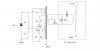
I am using a very simple two transistor (KSE13009L ,700Vcbo 400Vceo 24A Icp), and two resistor oscillator circuit to provide 24v ac to a coil, the coil is 10 turns 18awg on a ferrite core(theres also a second coil providing feedback to the transistors but that is irrelivant to my question), the circuit has to be powered from a 24v lead acid cell..... no other option is feasable.
I designed this oscillator to use the least components possible and be as simple as physically possible.... it has to stay that way due to the insane rf and flux the bits on the other end of the ferrite core generate! more bits = more interferrence + more popped stuff...

Due to the insanely low "H" of the 10 turn coil it is effectively a dead short on the transistors, hence my problem..... CURRENT LIMITTING!!!

as you know a low ohm (1k8) high watt (10w) resistor still glows red hot delivering 6A,
and I need to limit the supply current to approx 6-20A (pref adjustable),using a resistor is not only hazardous but inefficient.
I have designed an adjustable current limiter based on the 2n3055 npn, it works , but delivers only 4A and still gets really hot.

has anyone got another (preff simple) supply limiting solution to keep the smoke in the transistors?

adjustabillity is prefferable but not essential.

Cheers :)

(P.S. I was using a more complex circuit using IRF520 mosfets which was self limmiting ....but the RF interference and back EMF surge of the secondary ensures a short lifespan despite protective circuitry! Hence the simple transistor curcuit, cheaper, easyer, and for reasons I cant easily explain, it survives the feedback of the secondary )
 
Last edited:
What is the application for your circuit? Can you post a schematic?
Sounds like you want a DC-DC converter... correct?
 
Last edited:
You can try using lamps. Cold thay have a low resistance. To much current and thay will get warm and incress in resistance. Andy
 
I don’t see where you state a frequency. Can you go to a higher frequency thus increasing the XL of the coil? Second possibility, put a cap in series with the coil to limit the operating current and bypass with a high value resister to provide a small bias current to get things started. Granted, not as theoretically efficient as your design but, it might do as an adequate work a round.
 
The coil is supposed to have inductance. The inductance is a high impedance at a high frequency so the current will automatically be reduced when there is no load.

For example look at a power transformer. It has very low resistance but does not get hot when it has no load.
 
Make your power oscillator current regulated. This can be done quite easily with a 2 transistor oscillator, there is a voltage boost circuit here that regulates around input current, so if input voltage is relatively fixed (like a 24v battery) then it will run at (relatively) fixed input power which can be ideal for voltage boost systems.

**broken link removed**

R2 sets the input current, it turns the osc off when the volts on R2 > 0.6v. So a 1 ohm resistor gives you about 0.6 amps.
 
schematic etc

sorry guys I should have mentioned its a flyback driver to be used to power an LC Tank circuit through protective circuitry and in turn another primary winding on a second transformer through a spark gap :) The frequency is determined by the inductance of L2, this circuit should technically settle into a state of self resonance, the output frequency is able to be altered slightly as the coils taps are adjustable by a winding at a time. Im after a separate limmiting circuit to be attached directly to the supply... Thanks for your input thus far :)


heres a rough schematic of the circuit...
 

Attachments

  • driver circuit.jpg
    driver circuit.jpg
    47.2 KB · Views: 276
Last edited:
good point audioguru, although effectively i want to limmit the current this coil can draw if i have a massive load on it... i realise the impedence rises with frequency but im hoping i can adjust this circuit to approx 70 -80 hz max which is quite low....
 
Last edited:
You can try using lamps. Cold thay have a low resistance. To much current and thay will get warm and incress in resistance. Andy

thanks... thought of this but efficiency is a must as this portable unit needs to be running as long as possible on display :)
 
I don’t see where you state a frequency. Can you go to a higher frequency thus increasing the XL of the coil? Second possibility, put a cap in series with the coil to limit the operating current and bypass with a high value resister to provide a small bias current to get things started. Granted, not as theoretically efficient as your design but, it might do as an adequate work a round.

thanks but frequency needs to remain quite low.... 70-80hz max otherwise my tank capacitor will need to be an impractical value for this design and the coils inductance is a set value giving a set oscillating frequency....
 
Last edited:
thanks but frequency needs to remain quite low.... 70-80hz max otherwise my tank capacitor will need to be an impractical value for this design and the coils inductance is a set value giving a set oscillating frequency....
A ferrite core is used at frequencies a thousand and a million times higher. No wonder the current is extremely high, your "transformer" is a dead short.
A laminated iron core is used in transformers with such a low frequency. With many turns of wire so that its inductance is high enough.
 
A ferrite core is used at frequencies a thousand and a million times higher. No wonder the current is extremely high, your "transformer" is a dead short.
A laminated iron core is used in transformers with such a low frequency. With many turns of wire so that its inductance is high enough.

yes i know,I stated at the beginning that it was a dead short on the transistors... unfortunately i cannot change the flybacks (LOPT) manufactured these days, its far too much to wind my own and the 10 turn primary has to be on the same ferrite core....besides , it needs this ratio and coupling as the idea is to generate as much back emf on the secondary as possible, while still supplying at least 30 ma. problem is the short, If i can limmit the input current without to manny losses this would be a breakthrough in portable tesla generators ...... they manage this with neon sign transformers at 50 Hz, which are already (and easily) current limmited due to the fact that they are AC input, Im basically trying to find out how to do the same with a DC transformer of a simillar type as the device has to be portable and im trying to limmit the input energy to a not-so-fatal level as is present in neon trannys......
 
Last edited:
Ive been told by a few fellow electronics engineers that what im trying to do is difficult/near impossible, especially reliably ,Im out to prove that wrong. remeber what they said about amplifier valves.... hence the semiconductor!
someone somewhere has the magic answer locked in there head and im trying to be a human can opener :)
 
Last edited:
The flyback transformer in a CRT colour TV operates at 15.734kHz in North America or 15.625kHz in Europe, not just 70-80Hz.
 
Your magic answer for 70 - 80 Hz operation with that circuit is to use a regular iron core transformer like that of a automotive battery charger or other similar device and use a second step up transformer to get up to the higher voltage the spark gap needs or you will need to rewind something like a microwave oven transformers primary to work on your 24 volt input.
 
A system similar to the circuit I posted above can be adapted to do what you need. It monitors the rise in current through the pimary of the transformer, then when the current > X it turns off and will generate a flyback event.

If you connect it with a 555 timer you can use the 555 to set the frequency and the circuit will produce one primary pulse of X peak amps per 555 timer cycle. The circuit I posted can be controlled on/off by connecting R1 to either +ve or Gnd.

Think of it like a car ignition coil, driven by a 555 and each pulse has a max primary current limited by the circuit. The transformer inductance is not critical.
 
The flyback transformer in a CRT colour TV operates at 15.734kHz in North America or 15.625kHz in Europe, not just 70-80Hz.

yes, but Im not using the origional primary or driver circuitry ,so I dictate the operating frequency depending on what I put in..... I realise Im not driving the LOPT at maximum efficiency, but the 70-80 Hz is what the rest of the circuit requires...
 
Last edited:
Due to the insanely low "H" of the 10 turn coil it is effectively a dead short on the transistors, hence my problem..... CURRENT LIMITTING!!!

Insanely low "H"??? You may want to revisit that idea... with a low H you wouldn't have a lot of "B" (especially with a gapped core) and you wouldn't be saturating the core and your current wouldn't be so high.
 
Status
Not open for further replies.

New Articles From Microcontroller Tips

Back
Top