Electro Tech is an online community (with over 170,000 members) who enjoy talking about and building electronic circuits, projects and gadgets. To participate you need to register. Registration is free. Click here to register now.
Welcome to our site! Electro Tech is an online community (with over 170,000 members) who enjoy talking about and building electronic circuits, projects and gadgets. To participate you need to register. Registration is free. Click here to register now.
How do i modify this circuit(s) so that i could obtain the wavelength on the oscilloscope? Or rather, how do i connect this circuit to the oscilloscope to obtain and analyse the wave?
Hi Erique,
You should be able to see the transmitter's output on a 'scope.
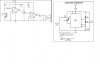
The transmitter frequency-modulates a 44kHz carrier. The Gwahaha receiver tries to amplify the 44khZ but the phototransistor, opamp and your hearing don't go that high. The receiver needs a fast photodiode and an opamp with a much higher bandwidth than just 9kHz like the old 741. A modern opamp like a TL071 has a 100kHz bandwidth and would work fine as a transimpedance amp. The receiver also needs an FM demodulator, not a differentiator.
I disagree. The 555 is freerunning, not triggered by another oscillator.
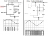
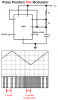
National calls this circuit a "Pulse Position Modulator", but its output sure looks like FM to me.
ok.. 'audio' .. the first pic is definitely a pwm .. but in the second the OFF times are fixed right ?.only the ON time varies .. so is it eqvivalent to fm ?
Both the receiver circuits need to have either dual supplies or a voltage divider to satisfy the common mode input voltage requirements of the op amps.
Both the receiver circuits need to have either dual supplies or a voltage divider to satisfy the common mode input voltage requirements of the op amps.
Good point! :lol:
If a voltage divider is used then the output of U1 in the Wahaha receiver needs a coupling capacitor to feed the volume control. Or else you won't hear the 40kHz. :wink:
Even my little dog can't hear that high. Bats?
Let's say I'm removing the audio input for the transmitter. Will I still obtain 44kHz on the scope? I think I can just play around with the capacitors and resistors to obtain an acceptable frequency. Instead of a speaker, i'll just connect the output of the receiver to the scope instead.
The laser diode might melt if you change the duty-cycle of the 555 that drives it without any current-limiting.
The receiver won't have an output with the opamp's pin 3 connected to pin 4.
Most of the projects on that guy's site don't work. Now his Pentium2 server doesn't work.
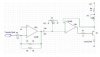
This driver circuit is actually designed for the first receiver. If i wanted to hook it up to a 100Mhz, what op amps should i use? Are there any major modifications needed for the receiver as well? I needed to get the waveform on an oscilloscope so that i could analyse the waveform.
This driver circuit is actually designed for the first receiver. If i wanted to hook it up to a 100Mhz, what op amps should i use? Are there any major modifications needed for the receiver as well? I needed to get the waveform on an oscilloscope so that i could analyse the waveform.
Please save and attach schematics as a clear GIF or PNG file type, instead of a fuzzy JPG that is used for photographs.
I don't know any opamp that works as high as 100MHz. A TL071 or TL081 works as high as 100kHz, but won't properly amplify a triangle waveform above about 10kHz. A TL072 and a TL082 are dual 100kHz opamps.
Since the 1st opamp has its non-inverting input grounded, then it needs a dual supply.
R8 in the 2nd opamp circuit has a value so high that it limits the max laser diode current so low that it might not work. The 2nd opamp circuit will work with a single or dual supply.
The receiver circuit doesn't show how its photodiode is connected so I don't know if it will work. It also has the non-inverting inputs of the opamps grounded so also needs a dual supply. A TL074 or a TL084 are quad 100kHz opamps.
This site uses cookies to help personalise content, tailor your experience and to keep you logged in if you register.
By continuing to use this site, you are consenting to our use of cookies.