Electro Tech is an online community (with over 170,000 members) who enjoy talking about and building electronic circuits, projects and gadgets. To participate you need to register. Registration is free. Click here to register now.
Welcome to our site! Electro Tech is an online community (with over 170,000 members) who enjoy talking about and building electronic circuits, projects and gadgets. To participate you need to register. Registration is free. Click here to register now.
You mean that in order to connect the 1-ohm resistor to the capacitor, i'll need to cut the a trace in the board?
I though about it but wasnt sure if thats what you meant.
If you want to do it with a scope all by itself, you will need a scope that can do trace math, and then average the results of the math operation.
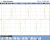
I've attached a scope capture showing the grid voltage and the current drawn by a compact fluorescent lamp. The CFL has a switching supply inside and draws very spiky current waveforms.
The scope is set up to show grid voltage on one channel and lamp current on another channel. The math function multiplies the two waveforms, and the the result is averaged.
The yellow trace is the grid voltage (120 VAC here in the U.S.), the green trace is the lamp current (measured across a 1 ohm resistor in series with the lamp), and the purple waveform is the product of the voltage and current.
The average of the purple waveform is shown at the bottom of the image; it's 23.8 watts.
If you can extract the captured waveforms from your scope, you could do the multiply and average with Mathcad, or some similar program.
To safely make a measurement like this, you need to use an isolation transformer, or use isolated differential probes, which is what I did.
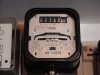
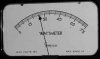
Another method to measure the true power is to use a wattmeter.
The second image shows the reading on an electromechanical wattmeter, showing 25.9 watts. The meter is only a 5% accuracy meter, so the reading is the same as the scope within the accuracy of both instruments.
...
1. You're actually saying that I can treat the current that comes from the capacitor as DC current, and the voltage on that capacitor as DC voltage; and then you get P = I * V .
Did i get you right?
2. I just dont quite understand why do you suggest to connect a large capacitor in parallel with the existing one?
Is it only to decrease the ripple current and voltage, and therefore being able to measure the true power as the product of two DC components (I and V) with better proximity?
3. Moreover, adding this large capacitor will only increase the apparent power that the SMPS consumes from the power plant, but wont change the true power the SMPS consumes from the power plant, right?
4. Why did you say the connect the resistor between the two capacitors, and not after them? we dont care about the current thats going to the capacitors, but only the current thats going to the system which the PSU drives.
If I understood your method right, then its a really good one, it relays on the fact that Pin = Pout (where Pin is the power that the power plant provides, and Pout is the power that the capacitor provides).
The capacitor itself also requires power from the power plant, but its reactive power therefore we dont need to measure it.
So I wonder why i was suggested to measure areas of curves which is such a hard work.
1. The current between the capacitors will represent the downstream current (into your buck converter). Sicne you will have the DC voltage and DC current this is basically measuring the input power into your buck converter, which is the item you need efficiency data for.
2. You got it. 2 large caps means very close to DC voltage, so both current and voltage are now easy to measure.
3. Worrying about power factor is just overcomplicating it. You said you have a single rectifier diode on the input, and buck regulator, both suggest you wanted a simple low parts count design rather than a design based on very high efficiencies. Get your buck regulator efficiency tuned good enough and go back to using whatever size cap you need for the final design.
4. You need 2 caps because the current drawn by the buck reg is in DC pulses of a low duty cycle, and to measure that as DC current you need 2 caps. This makes a DC voltage at both ends of the current sense resistor, ie a DC voltage across the resistor, so you now have a DC voltage and DC current you can measure.
Ultimately if you want to make a more eficient design you will need better test equipment and a different more complex design; like an isolated forward converter or push pull smps. But for now you can get DC volts and current into the buck reg and DC volts and current out, so you can build it and see if it's close to what you need.
This site uses cookies to help personalise content, tailor your experience and to keep you logged in if you register.
By continuing to use this site, you are consenting to our use of cookies.
 - but I can't see a flaw in it?.