Continue to Site

Welcome to our site!

Electro Tech is an online community (with over 170,000 members) who enjoy talking about and building electronic circuits, projects and gadgets. To participate you need to register. Registration is free. Click here to register now.

  • Welcome to our site! Electro Tech is an online community (with over 170,000 members) who enjoy talking about and building electronic circuits, projects and gadgets. To participate you need to register. Registration is free. Click here to register now.

How to make Oscillator Variable

Status
Not open for further replies.

yasir_ali

New Member
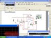
hey! Guys I've designed a phase-shift oscillator. now i want to make it variable frequency oscillator.? what should i do.? what i think is to use a single variable resistor instead of three fixed resistors, but i don't know is there any type of variable resistor available. look at the picture.
 

Attachments

  • phase_shift_oscillator._5754.jpg
    phase_shift_oscillator._5754.jpg
    85.8 KB · Views: 257
Last edited:
Your simple oscillator does not have an amplitude stabilizer so its output clips.

My phase-shift oscillator uses a triple-gang variable resistor for tuning.
It has low-pass RC filters instead of the high-pass ones you use so the amplifier stage that clips is filtered 3 times by the RC filters for very low distortion and a fixed output level.
 
i don't know why i can't your reply here coz my subscription shows that i've received reply but it's not showing it.what should i do.?
 
i have changed three fixed resistors with a triple ganged variable resistor. now i don't know how to stablize the gain of the oscillator.
 
You need to learn about the phase-shift oscillator including how to stabilize its output level with a light-bulb, a Fet transistor or diodes.
 
Hello again,


Here are a couple of root locus plots for your original circuit. The first plot shows a more continuous graph but it's harder to pick out the right value of K where the plot crosses the imaginary axis, so the second plot was done with K stepping by 5k for each dot, starting at 10k. The values labeled on the plot are in k ohms.
Looking at the second plot which also has values of K labeled, we can see that the locus crosses the imaginary axis near the point where K is approximately equal to 26.5k. We can then read off the jw frequency from the imaginary axis, divide by 2*pi, and get the frequency, which comes out in the neighborhood of 1000Hz. Higher resolution would get us closer to the exact value, but this plot was done assuming a perfect op amp anyway so the real life value of K required for oscillation would be a bit higher. Still, it's interesting to look at the plot and see what information we can get from it.
 

Attachments

  • PhaseShiftOsc01.gif
    PhaseShiftOsc01.gif
    8.1 KB · Views: 225
  • PhaseShiftOsc02.gif
    PhaseShiftOsc02.gif
    8 KB · Views: 220
Last edited:
Hi,

I am not using it, just analyzing it.
 
Status
Not open for further replies.

Latest threads

New Articles From Microcontroller Tips

Back
Top