Continue to Site

Welcome to our site!

Electro Tech is an online community (with over 170,000 members) who enjoy talking about and building electronic circuits, projects and gadgets. To participate you need to register. Registration is free. Click here to register now.

  • Welcome to our site! Electro Tech is an online community (with over 170,000 members) who enjoy talking about and building electronic circuits, projects and gadgets. To participate you need to register. Registration is free. Click here to register now.

How to make my comparator works (HIGH) when it only sees 47Kohm not the other value?

Status
Not open for further replies.

qq8807

New Member
Good day !!!

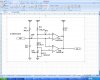
I am designing a comparator circuit that need to add the hysteresis.

It will be used to detect the existence of 47Kohm resistor at the input before the comparator gives High Output to turn ON another IC at the output.

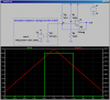
Few test circuits have been developed, but I still can't get a correct desirable output. When i vary the resistance to more than 47Kohm, the output of comparator will be always HIGH. When i vary the resistance to lower beyond than 47Kohm (i.e 1Kohm) then the output of the comparator will be only Low.

This is beyond than what I expect!!

Suppose, the circuit should give HIGH output when the resistance at the input is 47Kohm with the tolerance of 5% only.

Please please please help me..... !!! :(
 
I think you want a window comparator. Post a schematic of one of your circuits, so we can get an idea of your power supply voltages, what type of comparator you want to use, etc. Alternately, you can just tell us this information.
A window comparator is easy to make. We just need to see what your resources are.
 
Last edited:
I think you want a window comparator. Post a schematic of one of your circuits, so we can get an idea of your power supply voltages, what type of comparator you want to use, etc. Alternately, you can just tell us this information.
A window comparator is easy to make. We just need to see what your resources are.

:( How can I post my scanned schematic ??
 
As Roff has said you may need a window comparator. BUT to be sure, could you post a schematic for others to see that may indicate the degree of hysteresis you are looking for to give you the results desired? You post lacks much information to give you a specific answer to your issue.

EDIT: Ate dinner and didn't update screen upon returning :eek:

Go to this link for directions to post your schematic:
 
Last edited:
you can use a wheastone bridge. make it balance when 47k is connected, for other values a dual voltage comparator can give you disired out put with settable hysteresis
 
Thank u very much WilliB !!:D

I attached the diagram, in theory it should work I guess.... :confused:

Would like to get a good advice.
 

Attachments

  • ID Detection_A25.JPG
    ID Detection_A25.JPG
    164.3 KB · Views: 158
Your posted circuit is as Roff suggested a Window Comparator. The window is determined by R32, R33 & R34. The upper limit is on pin 5 of U3A (Test Point 41) and the lower limit is on pin 6 U3B. Anytime the voltage at test point 40 is within the window the output (CE-1) will be high. R31 serves as half of a voltage divider based on what the PID resistance is to ground. What doesn't work about the circuit? As drawn it should work fine.

Ron
 
Here is simpler way to do it. Single opamp or comparator. Has settable amount of hysteresis.

Note how LTSpice can model a time-varying resistance: create a time varying voltage, and then make the resistance vary in step with the voltage. Red trace shows the varying (sensor) resistance. The green trace is the output. If you want the output to go the other way, swap the position of R2/R3.
As shown, the cutin resistance is 48K, and the cutout resistance is 46K.
 

Attachments

  • DF101.png
    DF101.png
    38.9 KB · Views: 148
Last edited:
Status
Not open for further replies.

Latest threads

New Articles From Microcontroller Tips

Back
Top