Electro Tech is an online community (with over 170,000 members) who enjoy talking about and building electronic circuits, projects and gadgets. To participate you need to register. Registration is free. Click here to register now.
Welcome to our site! Electro Tech is an online community (with over 170,000 members) who enjoy talking about and building electronic circuits, projects and gadgets. To participate you need to register. Registration is free. Click here to register now.
Hello there :
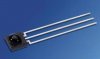
I have payed : an IR LED & IR Receiver
I want make the ray between the IR LED & IR Receiver
as a switch to open and close the circuit
I want it simple cus the circuit have many functions
the circuit Gary B suggested contains a visible light receiver (LDR).
Your receiver chip looks more like a TSOP582X (Vishay) which is sensitive to UV-light.
The chip contains signal amplifier and a automatic gain control circuit (AGC).
Using a transmitter emitting UV light steadily the receiver reduces sensitivity by AGC.
You should transmit bursts of equal 600µs length and pauses using the carrier frequency the chip is designed for (30 through 56KHz).
Refer to the data sheet of the receiver circuit to optimize the transmitter.
A transmitter can be built around two (or a dual) NE555. The dual version is the NE556.
Control the carrier oscillator by the first circuit which turns on the second every 1,200µs with 600µs burst length.
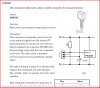
If the transmitter circuit has to work accurately you might use a crystal oscillator. Frequency deviation of ±5KHz from the nominal receiver frequency is no problem. Receiver circuits are not narrow banded.
Here is a circuit design using a crystal oscillator.
the circuit Gary B suggested contains a visible light receiver (LDR).
Your receiver chip looks more like a TSOP582X (Vishay) which is sensitive to UV-light.
The chip contains signal amplifier and a automatic gain control circuit (AGC).
Using a transmitter emitting UV light steadily the receiver reduces sensitivity by AGC.
You should transmit bursts of equal 600µs length and pauses using the carrier frequency the chip is designed for (30 through 56KHz).
Refer to the data sheet of the receiver circuit to optimize the transmitter.
A transmitter can be built around two (or a dual) NE555. The dual version is the NE556.
Control the carrier oscillator by the first circuit which turns on the second every 1,200µs with 600µs burst length.
If the transmitter circuit has to work accurately you might use a crystal oscillator. Frequency deviation of ±5KHz from the nominal receiver frequency is no problem. Receiver circuits are not narrow banded.
Here is a circuit design using a crystal oscillator.
OK, you want to make a switch works on I.R. this is not so much complex it is easy :-
take 555 IC and set it freq. upto 38khz which is best for it....
now how to make pulse from it..?? read the data sheet of 555 IC
First check this then i will tell you next step.......place a Buzzer to check it is working or not, LED will work in low freq. only..!!
Plan B could be to use 2 picaxe chips as they have IR abilitys built in, and will interface directly with the IR sensor you have.
Or 1 picaxe chip and a sony remote control from a tv or something as the picaxe has the sony IR protocol built into it.
This site uses cookies to help personalise content, tailor your experience and to keep you logged in if you register.
By continuing to use this site, you are consenting to our use of cookies.