hesam_m
Member
The negative voltage provision is necessary for some circuits. Usually, the best and cheap option is to use a switching voltage converter. Sometimes the power consumption on the negative rail is high, therefore selecting the LM2576 could be a good choice.
The LM2576 series of regulators are monolithic integrated circuits that provide all the active functions for a step-down (buck) switching regulator, capable of driving 3A load with excellent line and load regulations. In this task, we used it as a positive to negative converter and regulator (buck-boost).
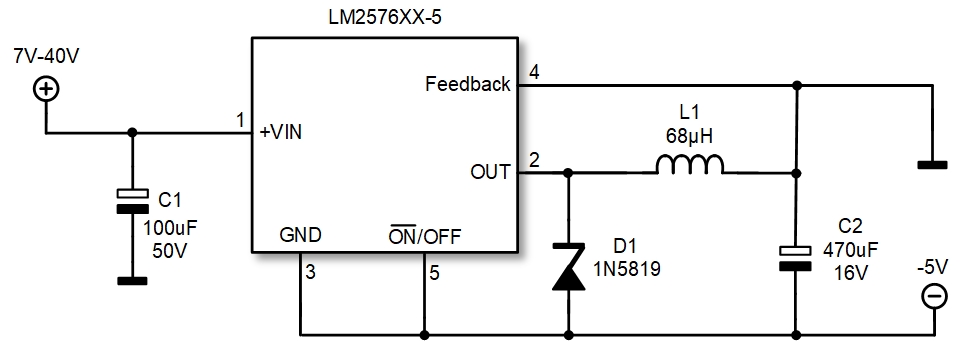
In this case, the fixed 5V regulator (LM2576-5) has been selected, but you are free to choose the 3.3V, 12V or 15V versions either. The regulator type selection (fixed output) does not make any specific change in the circuit.
Below is the schematic diagram of the regulator.
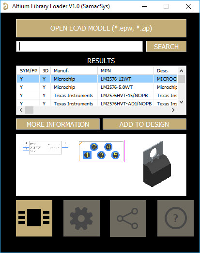
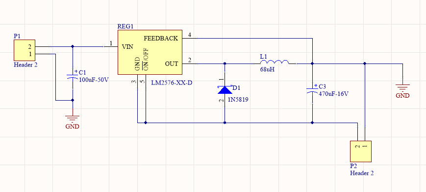
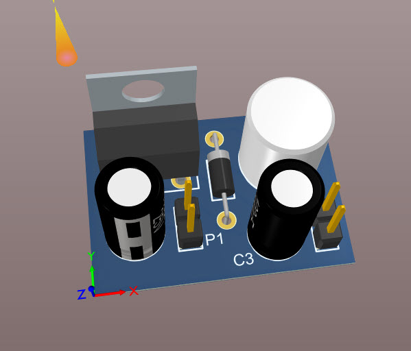
I have used the Altium designer CAD to design a PCB for the circuit. I did not have the footprint of the LM2576, therefore I used the Samacsys Altium plugin to find the available footprint.
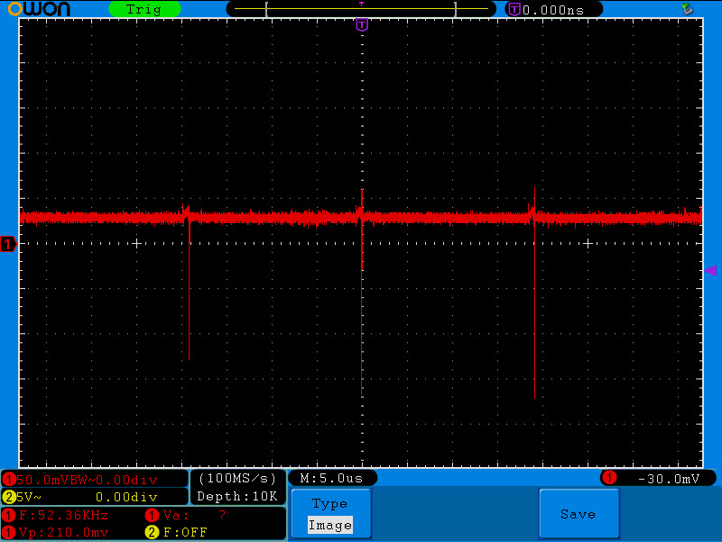
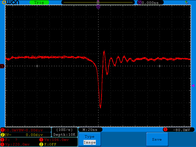
I built the circuit and tested the output. The voltage is fixed at 5.03V. To check the switching noises, I used the oscilloscope in the AC mode, 50mV division. As the figures imply, the switching noise frequency is around 52KHz and the amplitude is around 210mVp-p.
I tried to implement an LC filter to reduce the output noise, but interestingly it did not reduce the noise! Maybe a capacitance multiplier could help but I did not try it, because one advantage of this circuit is a high current delivery (if I don’t mistake, it can be around 400mA) and using the capacitance multiplier can reduce the output current or introduce a voltage drop.
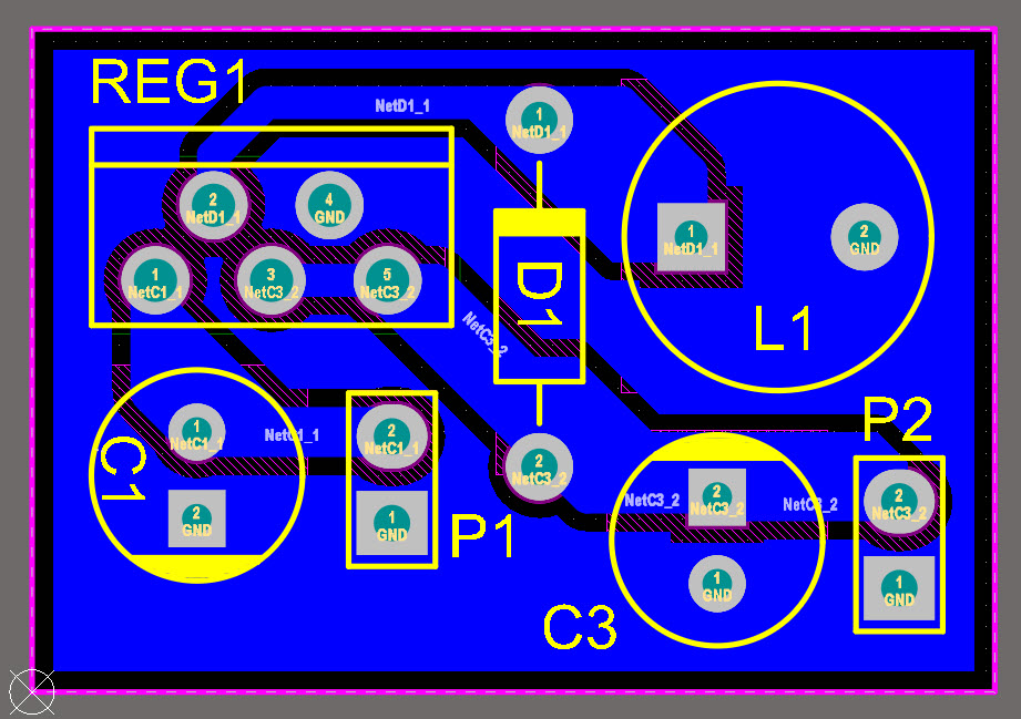
I’ve attached the Altium files. The board is a single layer PCB. You can modify it with SMD parts or change it based on your own needs.
The LM2576 series of regulators are monolithic integrated circuits that provide all the active functions for a step-down (buck) switching regulator, capable of driving 3A load with excellent line and load regulations. In this task, we used it as a positive to negative converter and regulator (buck-boost).
In this case, the fixed 5V regulator (LM2576-5) has been selected, but you are free to choose the 3.3V, 12V or 15V versions either. The regulator type selection (fixed output) does not make any specific change in the circuit.
Below is the schematic diagram of the regulator.
I have used the Altium designer CAD to design a PCB for the circuit. I did not have the footprint of the LM2576, therefore I used the Samacsys Altium plugin to find the available footprint.
I built the circuit and tested the output. The voltage is fixed at 5.03V. To check the switching noises, I used the oscilloscope in the AC mode, 50mV division. As the figures imply, the switching noise frequency is around 52KHz and the amplitude is around 210mVp-p.
I tried to implement an LC filter to reduce the output noise, but interestingly it did not reduce the noise! Maybe a capacitance multiplier could help but I did not try it, because one advantage of this circuit is a high current delivery (if I don’t mistake, it can be around 400mA) and using the capacitance multiplier can reduce the output current or introduce a voltage drop.
I’ve attached the Altium files. The board is a single layer PCB. You can modify it with SMD parts or change it based on your own needs.
Attachments
Last edited:
