Continue to Site

Welcome to our site!

Electro Tech is an online community (with over 170,000 members) who enjoy talking about and building electronic circuits, projects and gadgets. To participate you need to register. Registration is free. Click here to register now.

  • Welcome to our site! Electro Tech is an online community (with over 170,000 members) who enjoy talking about and building electronic circuits, projects and gadgets. To participate you need to register. Registration is free. Click here to register now.

How to limit Vout of an opamp

Status
Not open for further replies.

oandac

New Member
Hi,

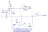
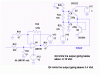
I use Opa129 as voltage to voltage coverter for high input impedance devices. Now I have to use an usb ADC card which requires max input Voltage of ±2.5 V . If one of the input voltage channels exceeds ±2.5 V limit, it disturbs other channel reading as well. Supply Voltage of OPA129 is ±9V or ±12 V. Input is bipolar. How can I limit the output voltage to ±2.5V. which Zenner? Which Diode?

Regards

Omer
 
What is the bandwidth of your input signal?
What is the sample rate of your ADC?
What is the input resistance and capacitance of your ADC?
The answers to these questions will help us come up with a solution.
 
Last edited:
The bandwidth of input signal changes depending on the sensor I use. Input voltage range: ±2.5 V or ±5 V , 0- 1kHz
But I also need to use Low-pass filter (after opa129) with cut-off frequency of 4Hz for static measurements(6 pole sallen-key works fine at the moment, with three CA3140 or Tl071 in series).

It is a data logger, 16 Hz per channel (16 channel, 24 bits,60 ms Conversion time for per channel)(https://www.picotech.com/precision-data-acquisition.html)

Input impedance of daq card: Differential: 2 MΩ Single ended: 1 MΩ

Im not expert on electronic as Im chemist. Sorry if Im asking it in a wrong way.

Omer
 
If the signals you are looking at vary by ±5 V, you'll need to halve the gain somewhere.

But, if you just want to clamp the thing - the typical configuration is to have a current limiting resistor and two series back-to-back zener diode.

(look at the second diagram from the top)
http://hyperphysics.phy-astr.gsu.edu/hbase/electronic/limiter.html

unfortunately the lowest voltage zeners I've used are 2.4V, so the clamping voltage would be 2.4V + .7V=3.1V, which exceeds the limits. However, the easy way is to just use a 2 strings of 3 standard switching diodes, which will limit the voltage to (3*.7V) = 2.1V
 
I think the knee on a zener, particularly a low-voltage zener, is much too soft to give you good limiting while not introducing nonlinearities in your signal path. I have an alternate idea, but it will require 4 op amps (could be in one package) plus a voltage reference chip. Wanna see it?
 
Please Ron. I would like to see it.

Im chemist and would like to improve my knowledge on electronics as Im academic person

Omer
 
OK, here it is.
 

Attachments

  • ADC protection.PNG
    ADC protection.PNG
    27.1 KB · Views: 246
This is how I protected the input to an ADC.
 

Attachments

  • protect.gif
    protect.gif
    26.5 KB · Views: 205
Status
Not open for further replies.

Latest threads

New Articles From Microcontroller Tips

Back
Top