Continue to Site

Welcome to our site!

Electro Tech is an online community (with over 170,000 members) who enjoy talking about and building electronic circuits, projects and gadgets. To participate you need to register. Registration is free. Click here to register now.

  • Welcome to our site! Electro Tech is an online community (with over 170,000 members) who enjoy talking about and building electronic circuits, projects and gadgets. To participate you need to register. Registration is free. Click here to register now.

How to Increase the Voltage From One Device to Another?

Status
Not open for further replies.

haroldjclements

New Member
Hello forum,

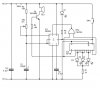
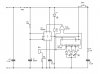
I am new to electronics and have only a basic idea in the area. However, I am keen learner and have produced a nice little timer alarm using the classic NE555 device coupled with a Decade Counter to display the countdown using LED's. Pin 3 (Output 0) of the Decade Counter is attached to the first input of a NOR gate, and Pin 11 (Output 9) is connected to the other input of the NOR gate. The output of this NOR gate is connected to in 4 (Reset) of the NE555. Thus if the Decade Counter is on either outputs 0 or 9 the supply to Pin 4 of the NE555 is cut stopping the pulse (there is a manual switch to force the Counter to tick over).

The Problem: I am only getting just over 1 volt from 11 (Output 9) which is not enough to activate the NOR gate. I have tried adding a transistor to increase the voltage but (this is where my knowledge lets me down) I have been unable to make it work. I have also tried an OP AMP but again have failed to get any increase in voltage.

If anyone could help me by way of a small drawing or an easily understandable descriptive answer I would be very much obliged. I have read so much about transistors but just can't seem to get my head around it.

Thank you for your time,
Harold Clements
 
Before all else a drawing would be nice? However, I ask some questions and maybe venture a guess. You don't mention the counter / divider but from the pins you mention I'll guess a 4017 or like.

OK, so you are clocking a 4017 using a 555 timer. You have LEDs hanging off the 4017. What voltage is powering the 555 and 4017? If you have LEDs hanging off the 4017 outputs do you have resistors in series with them? Actually you only need one resistor for all LEDs assuming you tie all LED cathodes together. The resistor value will be determined by the voltage to the 4017.

Because you are only seeing about a volt I am guessing you are loading the outputs too much with the LEDs.

Ron
 
First of all, I would like to thank you Ron for taking time in answering my question. Apologies for not including a drawing, I was at work when I posted the original message and did not have access to it.

You were correct with you guesses, I am using a 4017 Decade Counter, and when I put a 10K resistor to the tied cathodes of the LEDs, I have a little over 8v and the NOR gate works a treat.
Now, I have gone a bit further and connected a 6-12v buzzer to Pin 11 of the 4017 so it now feeds a both the afore mentioned buzzer and one of the inputs of the NOR gate. The NOR gate is still working fine. However, the buzzer does not sound. I believe that this may be down to the fact that I only have 320µA feeding the buzzer (8 volts).

Please note: after I included that buzzer, the LEDs were very dim so I moved the 10K resistor to the negative side of the buzzer which restored the brightness without dropping the voltage.

This time, I have included a drawing. There is probably a lot of basic errors in my implementation. I am open to all constructive criticism. However, please inform me of why it is wrong as I am very keen to learn from my mistakes.

Thanks again for your reply.
Kind Regards,

Harold Clements
 

Attachments

  • NE555_Timer.jpg
    NE555_Timer.jpg
    76.4 KB · Views: 288
Hi Ya Harold

OK, before I forget. The 4017 has been around forever and is a pretty useful chip. However, when we use it we need to remember it is an early CMOS chip and the source current on the output pins is really limited. Placing LEDs that consume low current on the output pins is something we can get away with. A buzzer may be pushing our luck. :)

This is the data sheet for the 4017.

Now in the drawing. OK, I understand you did place a 10K resistor between the LED common cathodes and ground. I am sure that gave the 4017 a sigh of relief. :) I am not sure what R1 and C4 are doing? C4 will charge through R1 and that is all it will do. I don't get that as drawn.

Something you could do is place about a 1K resistor in series with R3 on the high side (9 Volts) and replace R3 with a 10K pot. That would give you a variable frequency.

Now is this circuit just for kicks or are you going somewhere with the idea?

Since the count outputs sequentially go high from the 4017 if you want a buzzer we could hang a 2N2222 or 2N3904 transistor out there to drive it. Just about any basic NPN switching transistor would work.

Glad things are improving. I suggest you read the data sheet to get a handle on how much current the 4017 can source.

Ron
 
Hello Ron, thank you again for your reply – it is very much appreciated.

I take your point with R1 / C4. I think they may have been left over from some failed attempt to do something many moons ago and I was too frightened to remove them just in case I broke something! This is yet another example of my lack of knowledge letting me down. I have remove them and all is fine – Thank you. (Please see new diagram).

Again, you have guessed where I was coming from. My plan is to use a variable resistor to control the buzzing frequency. Basically, I am trying to create a timer alarm for my father who is getting on in years and needs to take an extraordinary amount of tablets at different times. By marking around the pot, the time intervals that he requires, he can (hopefully) just move the dial and press the button. He did have an alarm clock with four times, but he needs more than four and could not successfully change the alarm with changing the actual time or doing something else that would mess up the system. One of his major ailments is that he has renal (kidney) failure. This requires him to have a bag of fluid drained from him and new bag put back (basically, the fluid does the same job as the kidneys). I want to use the LEDs to signify how long he has until the next lot of medication so he can plan his time. However, as the first prototype, I was thinking to just making a food times of something that I could test accuracy.

I have taken your advice and used a transistor to boost the current going the buzzer. This is a basic electronics question – when playing the value of R4 I noticed that the higher resistance I used, the smaller the amps, the higher the voltage. Is this common behaviour for a transistor or is this just the way in which I have implemented the design? If so, does that mean that it is always a trade-off voltage and current? Also, by putting a resistor (R3) before the pot, will that be the lowest resistance charging C1 – if VR1 (100K) was turned down the 0% then do I have 10K feeding C1, if VR1 was 100%, would I be charging C1 through 110K resistance?

Again, I would like to thank you for your time and effort.

Kind Regards,
Harold Clements
 

Attachments

  • NE555_Timer_v2.jpg
    NE555_Timer_v2.jpg
    73.6 KB · Views: 306
Last edited:
Hi Ya Harold

I have taken your advice and used a transistor to boost the current going the buzzer. This is a basic electronics question – when playing the value of R4 I noticed that the higher resistance I used the smaller the amps, the higher the voltage. Is this common behaviour for a transistor, or is this just the way in which I have implemented the design? If so, does that mean that it is always a trade-off voltage and current? Also, my putting a resistor (R3) before the pot, will be the lowest resistance charging C1 – if VR1 (100K) was turned down the 0% then do I have 10K feeding C1, if VR1 was 100%, would I be charging C1 through 110K resistance?

OK, something we need to note here is that we are using the transistor as a switch. The whole purpose of the transistor is to turn on the buzzer. Basically when we apply a voltage to the base of the transistor through R4 we want to drive the transistor into saturation or as on as it gets. :)

For simple purposes the voltage drop across the transistor will be zero volts between the emitter and collector. Like a closed switch. We can have a problem though. The transistor is only rated for so much current. Too much current and it will get very hot to the touch and finally become toast. This is where we need to know for the given voltage how much our buzzer draws. Then we place a resistor in series with the buzzer and transistor to limit the current through the circuit.

Give this link a read to better understand what I am getting at. You could likely reduce R4 considerably.

More Later as I have to go....

Ron
 
Status
Not open for further replies.

Latest threads

New Articles From Microcontroller Tips

Back
Top